Removal [12/2019 - 11/2023]: Procedure
- REMOVE FRONT WHEELS
Refer to REMOVAL [12/2019 - 10/2022] , or refer to REMOVAL [10/2022 - ]
- REMOVE FRONT WHEEL OPENING EXTENSION PAD LH
Refer to PROCEDURE - Step 7 [12/2019 - 10/2022] , or refer to PROCEDURE - Step 7 [10/2022 - 11/2023]
- REMOVE FRONT WHEEL OPENING EXTENSION PAD RH
Refer to PROCEDURE - Step 8 [12/2019 - 10/2022] , or refer to PROCEDURE - Step 8 [10/2022 - 11/2023]
- REMOVE NO. 1 ENGINE UNDER COVER
Refer to PROCEDURE - Step 9 [12/2019 - 10/2022] , or refer to PROCEDURE - Step 9 [10/2022 - 11/2023]
- REMOVE NO. 2 ENGINE UNDER COVER ASSEMBLY
Refer to PROCEDURE - Step 10 [12/2019 - 10/2022] , or refer to PROCEDURE - Step 10 [10/2022 - 11/2023]
- REMOVE FRONT FENDER APRON SEAL LH
Refer to PROCEDURE - Step 11 [12/2019 - 10/2022] , or refer to PROCEDURE - Step 11 [10/2022 - 11/2023]
- REMOVE FRONT FENDER APRON SEAL RH
Refer to PROCEDURE - Step 12 [12/2019 - 10/2022] , or refer to PROCEDURE - Step 12 [10/2022 - 11/2023]
- DRAIN HYBRID TRANSAXLE FLUID
Refer to PROCEDURE - Step 5
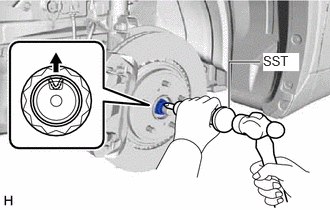
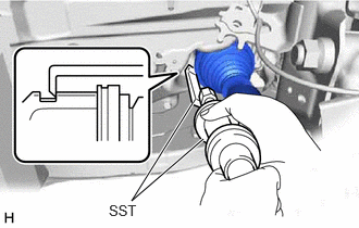
- REMOVE FRONT AXLE SHAFT NUT
- Using SST and a hammer, release the staked part of the front axle shaft nut.
- SST: 09930-00010
NOTE:Fully loosen the staked part of the front axle shaft nut, otherwise the threads of the drive shaft may be damaged.
- While applying the brakes, using a 30 mm deep socket wrench, remove the front axle shaft nut.
- Using SST and a hammer, release the staked part of the front axle shaft nut.
- SEPARATE FRONT SPEED SENSOR
Refer to PROCEDURE - Step 4 [12/2019 - 10/2022] , or refer to PROCEDURE - Step 4 [10/2022 - 11/2023]
- SEPARATE TIE ROD ASSEMBLY
Refer to PROCEDURE - Step 6 [12/2019 - 10/2022] , or refer to PROCEDURE - Step 6 [10/2022 - 11/2023]
- SEPARATE FRONT STABILIZER LINK ASSEMBLY
Refer to PROCEDURE - Step 11 [12/2019 - 10/2022] , or refer to PROCEDURE - Step 11 [10/2022 - 11/2023]
- SEPARATE FRONT LOWER NO. 1 SUSPENSION ARM SUB-ASSEMBLY
Refer to PROCEDURE - Step 8 [12/2019 - 10/2022] , or refer to PROCEDURE - Step 8 [10/2022 - 11/2023]
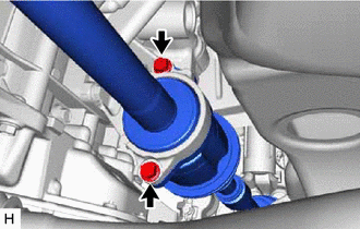
- SEPARATE FRONT DRIVE SHAFT ASSEMBLY
Refer to PROCEDURE - Step 9 [12/2019 - 10/2022] , or refer to PROCEDURE - Step 9 [10/2022 - 11/2023]
- REMOVE FRONT DRIVE SHAFT ASSEMBLY LH
- REMOVE FRONT DRIVE SHAFT ASSEMBLY RH
- Remove the 2 bolts and pull out the drive shaft together with the drive shaft bearing case sub-assembly.
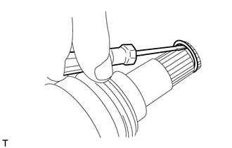
- Remove the front drive shaft assembly RH from the drive shaft bearing bracket.NOTE:
- Do not damage the front drive shaft oil seal RH.
- Do not damage the front axle inboard joint boot.
- Do not drop the front drive shaft assembly RH.
HINT:
If it is difficult to disengage the fitting, tap the end of the front drive inboard joint assembly with a brass bar and a hammer.
- Remove the 2 bolts and pull out the drive shaft together with the drive shaft bearing case sub-assembly.
- REMOVE FRONT DRIVE SHAFT HOLE SNAP RING