Removal [11/2023 - ]: Procedure
- PRECAUTION NOTE:
After turning the ignition switch off, waiting time may be required before disconnecting the cable from the negative (-) auxiliary battery terminal. Therefore, make sure to read the disconnecting the cable from the negative (-) auxiliary battery terminal notices before proceeding with work.
- REMOVE BATTERY SERVICE HOLE COVER (for HV Model)
Refer to PROCEDURE - Step 2
- DISCONNECT CABLE FROM NEGATIVE AUXILIARY BATTERY TERMINAL
for T24A-FTS:
Refer to PROCEDURE - Step 2
for A25A-FXS:
Refer to PROCEDURE - Step 3
- REMOVE REAR POWER WINDOW REGULATOR SWITCH ASSEMBLY WITH REAR DOOR UPPER ARMREST BASE PANEL
Refer to PROCEDURE - Step 4
- REMOVE REAR DOOR INSIDE HANDLE BEZEL
Refer to PROCEDURE - Step 5
- REMOVE REAR DOOR TRIM BOARD SUB-ASSEMBLY
Refer to PROCEDURE - Step 6
- REMOVE REAR DOOR SERVICE HOLE COVER
Refer to PROCEDURE - Step 19
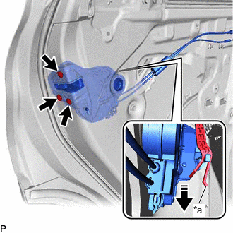
- REMOVE REAR DOOR LOCK WITH MOTOR ASSEMBLY
- Using a T30 "TORX" socket wrench, remove the 3 screws.
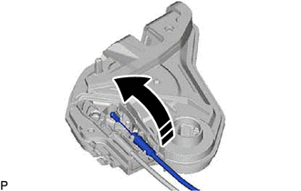
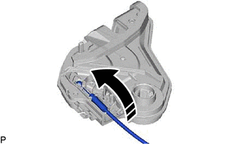
*a Release Plate 
Remove in this Direction - Move the rear door lock with motor assembly downward as shown in the illustration to disconnect it from the release plate of the rear door outside handle frame sub-assembly, and remove the rear door lock with motor assembly.
- When reusing the rear door lock with motor assembly:
- Using a T30 "TORX" socket wrench, remove the 3 screws.
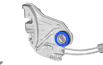
- REMOVE REAR DOOR LOCK COVER SUB-ASSEMBLY
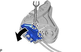
- REMOVE REAR DOOR LOCK REMOTE CONTROL CABLE ASSEMBLY
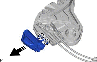
- REMOVE REAR DOOR INSIDE LOCKING CABLE ASSEMBLY