Installation [12/2019 - ]: Procedure
- INSTALL SHIFT LEVER POSITION SENSOR
- Move the shift lever to N.
- Temporarily install the shift lever position sensor to the hybrid vehicle transaxle assembly with the 2 bolts.NOTE:
- Do not reuse the shift lever position sensor if it has been dropped or subjected to a severe impact.
- Do not allow moisture to adhere to the connector terminal.
- Install the lock plate to the shift lever position sensor with the lock nut.
Torque: 6.9 N.m (70 kgf/cm, 61 in.lbf)
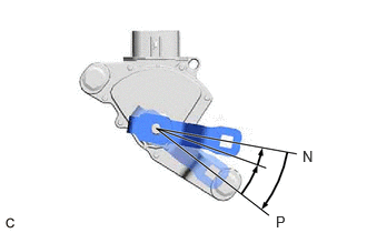
- Temporarily install the control shaft lever to the shift lever position sensor.
- Turn the control shaft lever clockwise until it stops, then turn it counterclockwise 2 notches.
- Remove the control shaft lever from the shift lever position sensor.
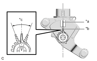
- Align the indicator with the neutral basic line.
*a Neutral Basic Line *b Indicator *c Range of Play NOTE:The indicator of the lock plate has a certain amount of play. Align the center point of the range of play with the neutral basic line.
- Tighten the 2 bolts.
Torque: 11 N.m (112 kgf/cm, 8 ft.lbf)
- Using a screwdriver with its tip wrapped with protective tape, secure the lock nut with the lock plate.
- Install the control shaft lever and washer to the shift lever position sensor with the nut.
Torque: 12.7 N.m (130 kgf/cm, 9 ft.lbf)
- Connect the shift lever position sensor connector.
- CONNECT TRANSMISSION CONTROL CABLE ASSEMBLY
- Engage the 2 claws to install a new clip to the transmission control cable assembly.
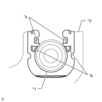
- Using a screwdriver, engage the 4 claws and connect the transmission control cable assembly to the No. 1 transmission control cable bracket.
*1 Transmission Control Cable Assembly *2 No. 1 Transmission Control Cable Bracket *a Claw (A) *b Claw (B) NOTE:- Make sure that the claws (A) of the clip are securely engaged in the grooves of the bracket.
- Make sure that the transmission control cable assembly is securely installed inside of the claws (B) of the clip.
- Connect the transmission control cable assembly to the control shaft lever with the nut.
Torque: 12 N.m (122 kgf/cm, 9 ft.lbf)
NOTE:Before installing the transmission control cable assembly, check that the shift lever position sensor and shift lever are in N.
- INSTALL AIR CLEANER ASSEMBLY WITH AIR CLEANER HOSE
Refer to PROCEDURE - Step 19 [12/2019 - 11/2023] , or refer to PROCEDURE - Step 19 [11/2023 - ]
- INSTALL INLET AIR CLEANER ASSEMBLY
Refer to PROCEDURE - Step 20 [12/2019 - 11/2023] , or refer to PROCEDURE - Step 20 [11/2023 - ]
- INSTALL COOL AIR INTAKE DUCT SEAL
Refer to PROCEDURE - Step 4 [12/2019 - 09/2020] , or refer to PROCEDURE - Step 4 [09/2020 - ]
- INSTALL NO. 1 ENGINE COVER SUB-ASSEMBLY
Refer to PROCEDURE - Step 66 [12/2019 - 10/2022] , or refer to PROCEDURE - Step 66 [10/2022 - 11/2023] , or refer to PROCEDURE - Step 64 [11/2023 - ]
- INSPECT SHIFT LEVER POSITION SENSOR POSITION
See step 2
- ADJUST SHIFT LEVER POSITION SENSOR POSITION
See step 3
- INSPECT SHIFT LEVER POSITION
See step 2
- ADJUST SHIFT LEVER POSITION
Refer to ADJUSTMENT [12/2019 - ]
- INSTALL NO. 2 ENGINE UNDER COVER ASSEMBLY
Refer to PROCEDURE - Step 62 [12/2019 - 10/2022] , or refer to PROCEDURE - Step 62 [10/2022 - 11/2023] , or refer to PROCEDURE - Step 60 [11/2023 - ]
- INSTALL NO. 1 ENGINE UNDER COVER
Refer to PROCEDURE - Step 63 [12/2019 - 10/2022] , or refer to PROCEDURE - Step 63 [10/2022 - 11/2023] , or refer to PROCEDURE - Step 61 [11/2023 - ]
- INSTALL FRONT WHEEL OPENING EXTENSION PAD RH
Refer to PROCEDURE - Step 65 [12/2019 - 10/2022] , or refer to PROCEDURE - Step 65 [10/2022 - 11/2023] , or refer to PROCEDURE - Step 63 [11/2023 - ]
- INSTALL FRONT WHEEL OPENING EXTENSION PAD LH
Refer to PROCEDURE - Step 64 [12/2019 - 10/2022] , or refer to PROCEDURE - Step 64 [10/2022 - 11/2023] , or refer to PROCEDURE - Step 62 [11/2023 - ]