Installation [12/2019 - 10/2022]: Procedure
- TEMPORARILY INSTALL AIR CONDITIONER UNIT ASSEMBLY
- Temporarily install the air conditioner unit assembly to the instrument panel reinforcement assembly with the 3 bolts.
- INSTALL CENTER HEATER TO REGISTER DUCT
- Engage the 6 claws to install the center heater to register duct.
- INSTALL INSTRUMENT PANEL REINFORCEMENT ASSEMBLY WITH AIR CONDITIONER UNIT ASSEMBLY NOTE:
- Be sure to support the air conditioner unit assembly when installing it. Failure to do so may cause the bracket of the air conditioner unit assembly to break.
- When installing the air conditioner unit assembly, eliminate static electricity by touching the vehicle body to prevent the components from being damaged.
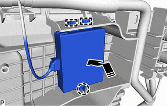
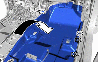
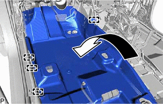
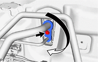
- Engage the 2 guides and claw to connect the ID code box (immobiliser code ECU) as shown in the illustration.

Install in this Direction - Connect the 4 connectors.
Install in this Direction - - - Engage each clamp.
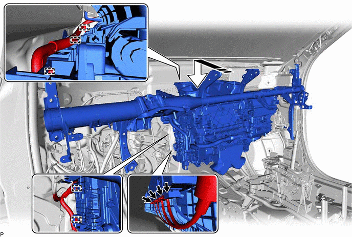
- Temporarily install the instrument panel reinforcement assembly with air conditioner unit assembly as shown in the illustration.
- Install the 4 bolts (A).

Bolt (A) 
Bolt (B) 
Nut - - Torque: 25 N.m (255 kgf/cm, 18 ft.lbf)
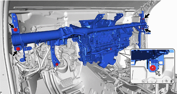
- Connect the brake pedal assembly with the bolt (B).
Torque: 15 N.m (153 kgf/cm, 11 ft.lbf)
- Temporarily install the nut.
- Install the 3 bolts.
Torque: 25 N.m (255 kgf/cm, 18 ft.lbf)
- Install the 2 hole plugs.
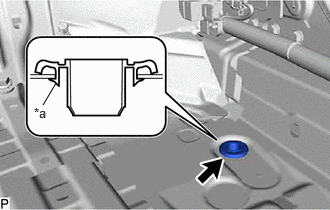
- Install a new cooler unit drain hose grommet.NOTE:
- If the drain cooler hose is disconnected from the cooler unit drain hose grommet, make sure to replace the cooler unit drain hose grommet with a new one. Failure to do so may lead to water ingress.
- Make sure that the entire lip of the cooler unit drain hose grommet is securely engaged to the vehicle body.
*a Lip - Connect the drain cooler hose.
- Install the clip.
- INSTALL NO. 2 INSTRUMENT PANEL BRACE SUB-ASSEMBLY
- Install the No. 2 instrument panel brace sub-assembly with the bolt and nut.
Bolt
Torque: 20 N.m (204 kgf/cm, 15 ft.lbf)
Nut
Torque: 18 N.m (184 kgf/cm, 13 ft.lbf)
- Temporarily install the screw.
HINT:
Do not fully tighten the screw.
- Install the No. 2 instrument panel brace sub-assembly with the bolt and nut.
- INSTALL NO. 1 INSTRUMENT PANEL BRACE SUB-ASSEMBLY
- Install the No. 1 instrument panel brace sub-assembly with the bolt and nut.
Bolt
Torque: 20 N.m (204 kgf/cm, 15 ft.lbf)
Nut
Torque: 18 N.m (184 kgf/cm, 13 ft.lbf)
- Temporarily install the screw.
HINT:
Do not fully tighten the screw.
- Install the No. 1 instrument panel brace sub-assembly with the bolt and nut.
- INSTALL AIR CONDITIONER UNIT ASSEMBLY
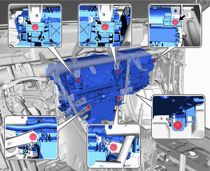
- Tighten the 3 bolts, 2 screws and nut to install the air conditioner unit assembly.
 Courtesy of © TOYOTA, LICENSE AGREEMENT TMS1002
Bolt Screw Nut - - Bolt
Torque: 9.8 N.m (100 kgf/cm, 87 in.lbf)
Nut
Torque: 9.8 N.m (100 kgf/cm, 87 in.lbf)
NOTE:Tighten the bolts, screws and nut in the order shown in the illustration.
- Tighten the 3 bolts, 2 screws and nut to install the air conditioner unit assembly.
- CONNECT INSTRUMENT PANEL WIRE
- Connect the earth wire with the bolt.
Torque: 10 N.m (102 kgf/cm, 7 ft.lbf)
- Engage each clamp.
- Connect the 2 connectors.
- Engage each clamp.
- Install the 2 nuts.
Torque: 5.0 N.m (51 kgf/cm, 44 in.lbf)
- Connect the connector holder with the bolt (B).
Torque: 12.5 N.m (127 kgf/cm, 9 ft.lbf)
- Connect the 4 earth wires with the 4 bolts (A).
Torque: 8.5 N.m (87 kgf/cm, 75 in.lbf)
- Connect the connector.
- Connect the earth wire with the bolt.
- INSTALL CENTER HEATER TO REGISTER SUB DUCT
- Engage the guide.
- Install the center heater to register sub duct with the 2 screws.
- INSTALL NO. 3 DASH PANEL INSULATOR PAD
- Install the No. 3 dash panel insulator pad.
- INSTALL REAR NO. 3 AIR DUCT
- Engage the 4 claws to install the rear No. 3 air duct.
- INSTALL REAR NO. 4 AIR DUCT
- INSTALL REAR NO. 1 AIR DUCT
- Engage the 4 claws to install the rear No. 1 air duct.
- INSTALL REAR NO. 2 AIR DUCT
- INSTALL ACCELERATOR PEDAL
Refer to PROCEDURE - Step 1
- INSTALL ACCELERATOR PEDAL PAD
Refer to PROCEDURE - Step 2
- INSTALL COOLER (ROOM TEMP. SENSOR) THERMISTOR
- Connect the aspirator and connector to install the cooler (room temp. sensor) thermistor.
- INSTALL NO. 1 CLEARANCE WARNING BUZZER
Refer to PROCEDURE - Step 1
- INSTALL PARKING ASSIST ECU WITH BRACKET
Refer to PROCEDURE - Step 3
- INSTALL ECU INTEGRATION BOX RH
Refer to PROCEDURE - Step 2
- INSTALL STEERING COLUMN ASSEMBLY
Refer to INSTALLATION [12/2019 - 10/2021] , or refer to INSTALLATION [10/2021 - 10/2022]
- INSTALL NO. 4 AIR DUCT SUB-ASSEMBLY
Refer to PROCEDURE - Step 4
- INSTALL METER MIRROR SUB-ASSEMBLY (w/ Headup Display)
Refer to INSTALLATION [12/2019 - ]
- INSTALL INSTRUMENT PANEL JUNCTION BLOCK ASSEMBLY WITH MAIN BODY ECU
Refer to INSTALLATION [12/2019 - 10/2022]
- INSTALL FRONT SEAT ASSEMBLY RH (for Manual Seat)
Refer to INSTALLATION [12/2019 - 10/2022]
- INSTALL FRONT SEAT ASSEMBLY (for Power Seat)
Refer to INSTALLATION [12/2019 - 10/2022]
- CONNECT INLET HEATER WATER HOSE B
- CONNECT OUTLET HEATER WATER HOSE B
- CONNECT COOLER REFRIGERANT LIQUID PIPE A
- Remove the vinyl tape from the cooler refrigerant liquid pipe A.
- Sufficiently apply compressor oil to a new O-ring and the fitting surface of the cooler refrigerant liquid pipe A.
Compressor Oil
ND-OIL 11 or equivalent
- Install the O-ring to the cooler refrigerant liquid pipe A.NOTE:
Keep the O-ring and O-ring fitting surface free of foreign matter.
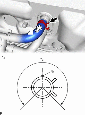
- Connect the cooler refrigerant liquid pipe A.
- CONNECT SUCTION PIPE SUB-ASSEMBLY
- Remove the vinyl tape from the suction pipe sub-assembly.
- Sufficiently apply compressor oil to a new O-ring and the fitting surface of the suction pipe sub-assembly.
Compressor Oil
ND-OIL 11 or equivalent
- Install the O-ring to the suction pipe sub-assembly.NOTE:
Keep the O-ring and O-ring fitting surface free of foreign matter.
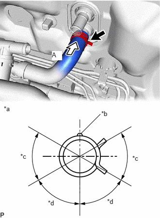
- Connect the suction pipe sub-assembly.
- Rotate the hook connector as shown in the illustration.
- Insert the tube joint into the fitting hole securely and install the bolt.
Torque: 9.8 N.m (100 kgf/cm, 87 in.lbf)
- INSTALL COWL VENTILATOR PANEL SUB-ASSEMBLY
Refer to PROCEDURE - Step 15
- INSTALL FRONT UPPER SUSPENSION TO COWL BRACE SUB-ASSEMBLY LH
Refer to PROCEDURE - Step 16
- INSTALL FRONT UPPER SUSPENSION TO COWL BRACE SUB-ASSEMBLY RH
HINT:
Perform the same procedure as for the LH side.
- INSTALL FRONT FENDER SPLASH SHIELD SEAL FRONT LH
Refer to PROCEDURE - Step 18
- INSTALL FRONT FENDER SPLASH SHEILD SEAL FRONT RH
HINT:
Perform the same procedure as for the LH side.
- INSTALL FENDER SPLASH SHIELD SUB-ASSEMBLY REAR LH
Refer to PROCEDURE - Step 20
- INSTALL FENDER SPLASH SHIELD SUB-ASSEMBLY REAR RH
HINT:
Perform the same procedure as for the LH side.
- INSTALL WINDSHIELD WIPER MOTOR AND LINK ASSEMBLY
Refer to INSTALLATION [12/2019 - ]
- ADD ENGINE COOLANT (for Engine)
Refer to PROCEDURE - Step 2
- INSPECT FOR COOLANT LEAK (for Engine)
Refer to PROCEDURE - Step 1
- CHARGE AIR CONDITIONING SYSTEM WITH REFRIGERANT
See step 2
- WARM UP COMPRESSOR
See step 4
- INSPECT FOR REFRIGERANT LEAK
See step 5