Installation [10/2022 - 11/2023]: Procedure
- INSTALL AIRBAG SENSOR ASSEMBLY
- Check that the ignition switch is off.
- Check that the cable is disconnected from the negative (-) auxiliary battery terminal.WARNING:
Wait at least 90 seconds after disconnecting the cable from the negative (-) auxiliary battery terminal to disable the SRS system.
- Install the airbag sensor assembly with the 3 bolts.
Torque: 17.5 N*m (178 kgf*cm, 13 ft.*lbf)
NOTE:- If the airbag sensor assembly has been dropped, or there are any cracks, dents or other defects in the case or connector, replace it with a new one.
- When installing the airbag sensor assembly, make sure that the wire harness does not interfere with other parts and is not pinched.
- When the ignition switch is first turned to ON after the airbag sensor assembly has been replaced, make sure that no one is in the vehicle.
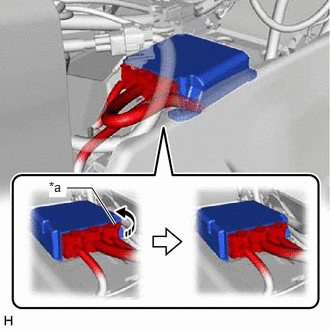
- Temporarily connect the connectors and then move the lock lever in the direction indicated by the arrow to securely connect the connectors.NOTE:
When connecting any airbag connector, take care not to damage the airbag wire harness.
*a Lock Lever 
Move in this Direction - Check that there is no looseness in the installed parts of the airbag sensor assembly.
- INSTALL FRONT NO. 2 CONSOLE BOX INSERT
Refer to PROCEDURE - Step 5
- INSTALL LOWER INSTRUMENT PANEL SUB-ASSEMBLY
Refer to PROCEDURE - Step 14
- INSTALL NO. 2 INSTRUMENT PANEL UNDER COVER SUB-ASSEMBLY
Refer to PROCEDURE - Step 15
- INSTALL COWL SIDE TRIM SUB-ASSEMBLY RH
HINT:
Use the same procedure as for the LH side.
Refer to PROCEDURE - Step 49
- INSTALL FRONT DOOR SCUFF PLATE RH
HINT:
Use the same procedure as for the LH side.
Refer to PROCEDURE - Step 50
- INSTALL CONSOLE BOX ASSEMBLY
Refer to INSTALLATION [10/2022 - ]
- CONNECT CABLE TO NEGATIVE AUXILIARY BATTERY TERMINAL
for T24A-FTS: Refer to PROCEDURE - Step 4
for A25A-FXS: Refer to PROCEDURE - Step 2
NOTE:When disconnecting the cable, some systems need to be initialized after the cable is reconnected.
Refer to INITIALIZATION [10/2022 - 11/2023]
- INSTALL BATTERY SERVICE HOLE COVER (for HV Model)
Refer to PROCEDURE - Step 3
- PERFORM DIAGNOSTIC SYSTEM CHECK
- INSPECT SRS WARNING LIGHT
Refer to OPERATION CHECK [10/2022 - 11/2023]
- PERFORM INITIALIZATION
for Electronically Controlled Brake System (for Gasoline Model): Refer to UTILITY [12/2019 - 11/2023]
for Stop and Start System: Refer to REGISTRATION [10/2022 - 11/2023]