Removal [12/2019 - 10/2022]: Procedure
- REMOVE SERVICE PLUG GRIP (for AWD)
Refer to REMOVAL [12/2019 - 10/2022]
- REMOVE NO. 2 INVERTER PROTECTOR (for AWD)
Refer to PROCEDURE - Step 9
- DISCONNECT ENGINE ROOM MAIN WIRE (for AWD)
Refer to PROCEDURE - Step 4
- REMOVE CONNECTOR COVER ASSEMBLY (for AWD)
Refer to PROCEDURE - Step 11
- CHECK TERMINAL VOLTAGE (for AWD)
Refer to PROCEDURE - Step 12
- INSTALL CONNECTOR COVER ASSEMBLY (for AWD)
Refer to PROCEDURE - Step 7
- CONNECT ENGINE ROOM MAIN WIRE (for AWD)
Refer to PROCEDURE - Step 31
- INSTALL NO. 2 INVERTER PROTECTOR (for AWD)
Refer to PROCEDURE - Step 17
- REMOVE REAR WHEEL
Refer to PROCEDURE - Step 1
- REMOVE TAIL EXHAUST PIPE ASSEMBLY
Refer to REMOVAL [12/2019 - 10/2022]
- REMOVE REAR SUSPENSION ARM COVER LH
See step 3
- REMOVE REAR SUSPENSION ARM COVER RH
HINT:
Perform the same procedure as for the LH side.
- REMOVE REAR AXLE SHAFT NUT LH (for AWD)
Refer to PROCEDURE - Step 4
- REMOVE REAR AXLE SHAFT NUT RH (for AWD)
HINT:
Perform the same procedure as for the LH side.
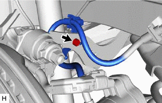
- SEPARATE REAR FLEXIBLE HOSE LH
- SEPARATE REAR FLEXIBLE HOSE RH
HINT:
Perform the same procedure as for the LH side.
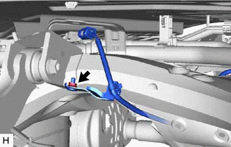
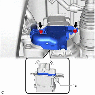
- DISCONNECT NO. 2 PARKING BRAKE WIRE ASSEMBLY (for AWD)
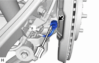
- Using a screwdriver with its tip wrapped with protective tape, disconnect the No. 2 parking brake wire assembly connector from the rear skid control sensor.
*a Protective Tape NOTE:- Remove any dirt or foreign matter on and around the No. 2 parking brake wire assembly connector before performing this step.
- Do not allow water, oil or dirt to enter the No. 2 parking brake wire assembly connector.
- Be careful not to damage the rear skid control sensor or connector cover.
- Using a screwdriver with its tip wrapped with protective tape, disconnect the No. 2 parking brake wire assembly connector from the rear skid control sensor.
- DISCONNECT NO. 1 PARKING BRAKE WIRE ASSEMBLY (for AWD)
HINT:
Perform the same procedure as for the LH side.
- REMOVE REAR SKID CONTROL SENSOR LH (for AWD)
Refer to PROCEDURE - Step 6
- REMOVE REAR SKID CONTROL SENSOR RH (for AWD)
HINT:
Perform the same procedure as for the LH side.
- REMOVE REAR HEIGHT CONTROL SENSOR SUB-ASSEMBLY LH (w/ Height Control Sensor)
Refer to REMOVAL [12/2019 - 11/2023]
- REMOVE REAR STABILIZER LINK ASSEMBLY LH
See step 4
- REMOVE REAR STABILIZER LINK ASSEMBLY RH
HINT:
Perform the same procedure as for the LH side.
- REMOVE REAR STABILIZER BAR
See step 6
- REMOVE REAR LOWER STABILIZER BRACKET
See step 7
- REMOVE REAR COIL SPRING LH
See step 5
- REMOVE REAR COIL SPRING RH
HINT:
Perform the same procedure as for the LH side.
- REMOVE REAR LOWER COIL SPRING INSULATOR LH
See step 6
- REMOVE REAR LOWER COIL SPRING INSULATOR RH
HINT:
Perform the same procedure as for the LH side.
- REMOVE REAR NO. 2 SUSPENSION ARM ASSEMBLY LH
See step 7
- REMOVE REAR NO. 2 SUSPENSION ARM ASSEMBLY RH
HINT:
Perform the same procedure as for the LH side.
- REMOVE REAR NO. 1 SUSPENSION ARM ASSEMBLY LH
See step 8
- REMOVE REAR NO. 1 SUSPENSION ARM ASSEMBLY RH
HINT:
Perform the same procedure as for the LH side.
- SEPARATE REAR UPPER CONTROL ARM ASSEMBLY LH
- SEPARATE REAR UPPER CONTROL ARM ASSEMBLY RH
HINT:
Use the same procedure as for the LH side.
- DRAIN HYBRID TRANSAXLE FLUID (for AWD)
Refer to PROCEDURE - Step 1
- REMOVE REAR DRIVE SHAFT ASSEMBLY LH (for AWD)
Refer to PROCEDURE - Step 15
- REMOVE REAR DRIVE SHAFT ASSEMBLY RH (for AWD)
HINT:
Use the same procedure as for the LH side.
- REMOVE REAR DRIVE SHAFT LH SNAP RING (for AWD)
Refer to PROCEDURE - Step 16
- REMOVE REAR DRIVE SHAFT RH SNAP RING (for AWD)
HINT:
Use the same procedure as for the LH side.
- SEPARATE FRAME WIRE (w/ Wire Harness)
- w/ Height Control Sensor:
- for AWD:
- for 2WD:
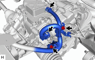
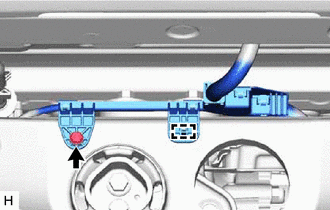
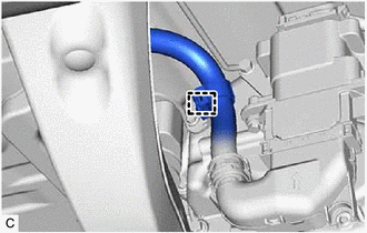
- DISCONNECT FLOOR UNDER WIRE (for AWD) WARNING:
Be sure to wear insulated gloves.
NOTE:Insulate the disconnected connectors with insulating tape.
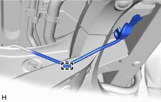
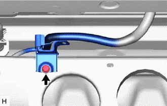
- Disengage the clamp.
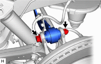
- Remove the 2 bolts and HV floor under wire from the rear traction motor with transaxle assembly.NOTE:
- Do not damage the terminals, interlock connector or rear traction motor with transaxle assembly during disconnection.
- Do not touch the waterproof seal or terminals of the connector.
- Do not allow any foreign matter or water to enter the rear traction motor with transaxle assembly.
- Although the connector may feel loose, this is not due to a malfunction.
*a Waterproof Seal
- Disengage the clamp.
- REMOVE REAR SUSPENSION MEMBER SUB-ASSEMBLY
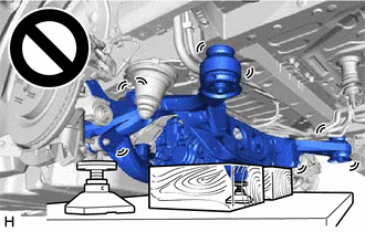
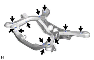
- Using an engine lifter, 2 attachments and 2 wooden blocks or equivalent tools, support the rear suspension member sub-assembly as shown in the illustration.WARNING:
- The rear suspension member sub-assembly is a very heavy component. Make sure that it is supported securely.
- If the rear suspension member sub-assembly is not securely supported, it may drop, resulting in serious injury.
NOTE:Use attachments and wooden blocks to keep the rear suspension member sub-assembly level.
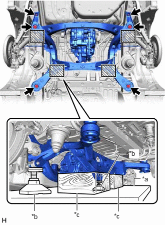
*a Engine Lifter *b Attachment *c Wooden Block 
Attachment and Wooden Block Placement Location - Remove the 4 bolts, 2 nuts, 2 rear lower suspension braces, rear lower suspension member stopper LH and rear lower suspension member stopper RH.
- Slowly lower the rear suspension member sub-assembly.NOTE:
When lowering the rear suspension member sub-assembly, be careful not to damage the vehicle body or other components installed to the vehicle.
- Using an engine lifter, 2 attachments and 2 wooden blocks or equivalent tools, support the rear suspension member sub-assembly as shown in the illustration.
- REMOVE REAR TRACTION MOTOR WITH TRANSAXLE ASSEMBLY (for AWD)
Refer to PROCEDURE - Step 4
- REMOVE REAR SUSPENSION MEMBER UPPER STOPPER
- REMOVE REAR SUSPENSION MEMBER LOWER STOPPER RETAINER
- REMOVE REAR UPPER CONTROL ARM ASSEMBLY LH
See step 2
- REMOVE REAR UPPER CONTROL ARM ASSEMBLY RH
HINT:
Perform the same procedure as for the LH side.
- REMOVE DIFFERENTIAL MOUNT CUSHION (for AWD)
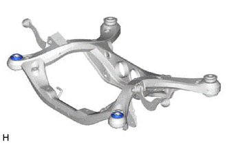
- REMOVE REAR SUSPENSION MEMBER FRONT BODY MOUNTING CUSHION (for LH Side)
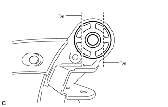
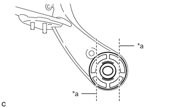
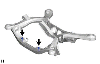
- Using a chisel and hammer, bend the 2 portions of the rear suspension member front body mounting cushion rib.NOTE:
Make sure to bend the 2 portions of the cushion rib until the claws of SST can fit securely.
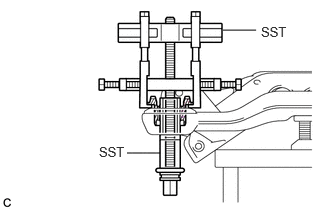
*a Bend Portion - Install SST as shown in the illustration.
- SST: 09830-10010
- 09830-01010
- 09830-01040
- 09830-01050
- SST: 09950-40011
- 09951-04020
- 09952-04010
- 09954-04010
- 09955-04051
- 09958-04011
NOTE:Apply molybdenum grease to the threads and tip of the SST center bolt before use.
- SST: 09830-10010
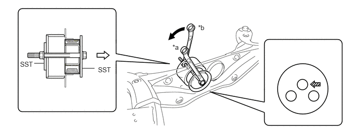
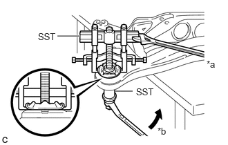
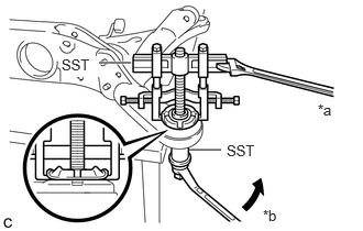
- Using SST, remove the rear suspension member front body mounting cushion while applying lubricant into the clearance between the rear suspension member front body mounting cushion and the rear suspension member sub-assembly.
- SST: 09830-10010
- 09830-01010
- 09830-01040
- 09830-01050
- SST: 09950-40011
- 09951-04020
- 09952-04010
- 09954-04010
- 09955-04051
- 09958-04011
NOTE:- Set the claws of SST onto the rear suspension member sub-assembly securely as shown in the illustration.
- Tighten SST slowly and evenly.
- Be careful as the rear suspension member front body mounting cushion may fly out.
- The rear suspension member front body mounting cushion cannot be reused.
*a Hold *b Turn - SST: 09830-10010
- Remove SST and the rear suspension member front body mounting cushion (LH Side) from the rear suspension member sub-assembly.
- Using a chisel and hammer, bend the 2 portions of the rear suspension member front body mounting cushion rib.
- REMOVE REAR SUSPENSION MEMBER FRONT BODY MOUNTING CUSHION (for RH Side)
HINT:
Perform the same procedure as for the LH side.
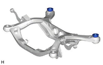
- REMOVE REAR SUSPENSION MEMBER REAR BODY MOUNT CUSHION LH
- Using a chisel and hammer, bend the 2 portions of the rear suspension member rear body mount cushion LH rib.NOTE:
Make sure to bend the 2 portions of the cushion rib until the claws of SST can fit securely.
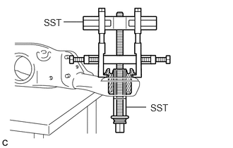
*a Bend Portion - Install SST as shown in the illustration.
- SST: 09830-10010
- 09830-01010
- 09830-01040
- 09830-01050
- SST: 09950-40011
- 09951-04020
- 09952-04010
- 09954-04010
- 09955-04051
- 09958-04011
NOTE:Apply molybdenum grease to the threads and tip of the SST center bolt before use.
- SST: 09830-10010
- Using SST, remove the rear suspension member rear body mount cushion LH while applying lubricant into the clearance between the rear suspension member rear body mount cushion LH and the rear suspension member sub-assembly.
- SST: 09830-10010
- 09830-01010
- 09830-01040
- 09830-01050
- SST: 09950-40011
- 09951-04020
- 09952-04010
- 09954-04010
- 09955-04051
- 09958-04011
NOTE:- Set the claws of SST onto the rear suspension member sub-assembly securely as shown in the illustration.
- Tighten SST slowly and evenly.
- Be careful as the rear suspension member rear body mount cushion LH may fly out.
- The rear suspension member rear body mount cushion LH cannot be reused.
*a Hold *b Turn - SST: 09830-10010
- Remove SST and the rear suspension member rear body mount cushion LH from the rear suspension member sub-assembly.
- Using a chisel and hammer, bend the 2 portions of the rear suspension member rear body mount cushion LH rib.
- REMOVE REAR SUSPENSION MEMBER REAR BODY MOUNT CUSHION RH
HINT:
Perform the same procedure as for the LH side.
- REMOVE BOLT (for 2WD)
- REMOVE HOLE PLUG