Installation [12/2019 - 11/2023]: Procedure
- INSTALL FLOOR UNDER WIRE WARNING:
Be sure to wear insulated gloves.
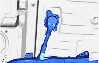
- for AWD:
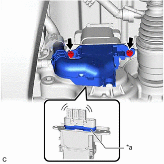
- Install the HV floor under wire to the rear traction motor with transaxle assembly with the 2 bolts.
*a Waterproof Seal Torque: 8.0 N.m (82 kgf/cm, 71 in.lbf)
NOTE:- Make sure that the connector is fully engaged.
- Do not damage the terminals, interlock connector or rear traction motor with transaxle assembly during installation.
- Do not touch the waterproof seal or terminals of the connector.
- Do not allow any foreign matter or water to enter the rear traction motor with transaxle assembly.
- Although the connector may feel loose, this is not due to a malfunction.
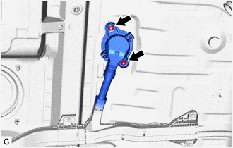
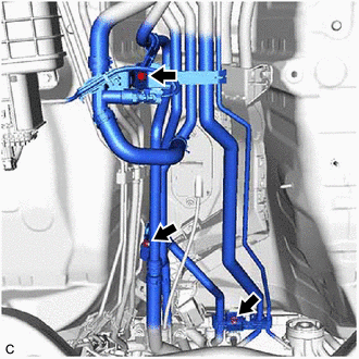
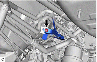
- Engage the clamp.
- Install the nut.
Torque: 8.0 N.m (82 kgf/cm, 71 in.lbf)
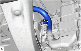
- Install a new clamp.
- Install the HV floor under wire to the rear traction motor with transaxle assembly with the 2 bolts.
- Install a new clamp.
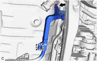
*a Grommet - Install the nut.
Torque: 8.0 N.m (82 kgf/cm, 71 in.lbf)
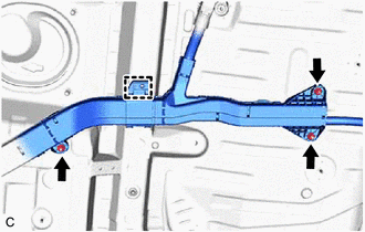
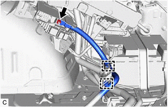
- Insert the HV floor under wire into the floor panel hole and engage the grommet.
- Insert the HV floor under wire into the floor panel hole and engage the grommet.
- Install the 2 nuts.
Torque: 8.0 N.m (82 kgf/cm, 71 in.lbf)
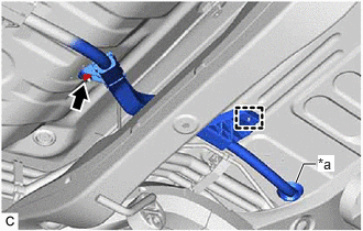
- Install a new clamp.
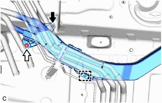
- Install the 3 nuts.
Torque: 8.0 N.m (82 kgf/cm, 71 in.lbf)
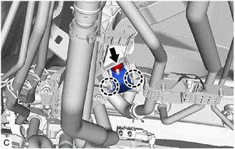
- Install the bolt and nut.
Torque: 8.0 N.m (82 kgf/cm, 71 in.lbf)
- Install a new clamp.
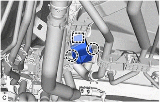
- Install 2 new clamps.
- Install the bolt and 2 nuts.
Torque: 8.0 N.m (82 kgf/cm, 71 in.lbf)
- Install the 2 nuts.
Torque: 8.0 N.m (82 kgf/cm, 71 in.lbf)
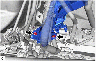
- Connect the engine room main wire to the HV floor under wire with the nut.
Torque: 8.0 N.m (82 kgf/cm, 71 in.lbf)
- Engage the 2 claws.
- Engage the guide and 2 claws to install the No. 1 terminal cap.
- Install the 2 nuts and bolt to connect the air conditioning tube assembly.
Torque: 5.4 N.m (55 kgf/cm, 48 in.lbf)
- Install the nut and connect the transmission control cable assembly.
Torque: 6.0 N.m (61 kgf/cm, 53 in.lbf)
- for AWD:
- INSTALL FRONT NO. 1 FLOOR HEAT INSULATOR
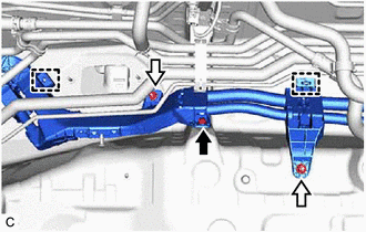
- Install the front No. 1 floor heat insulator with the 3 nuts.
Torque: 4.9 N.m (50 kgf/cm, 43 in.lbf)
- Install the front No. 1 floor heat insulator with the 3 nuts.
- INSTALL REAR MAIN MUFFLER HEAT INSULATOR SUB-ASSEMBLY
- Install the rear main muffler heat insulator sub-assembly with the 3 nuts.
Torque: 4.9 N.m (50 kgf/cm, 43 in.lbf)
- Install the rear main muffler heat insulator sub-assembly with the 3 nuts.
- INSTALL NO. 3 EXHAUST PIPE SUPPORT BRACKET
- Install the No. 3 exhaust pipe support bracket with the 2 bolts.
Torque: 29 N.m (296 kgf/cm, 21 ft.lbf)
- Install the No. 3 exhaust pipe support bracket with the 2 bolts.
- INSTALL NO. 4 EXHAUST PIPE SUPPORT BRACKET
- Install the No. 4 exhaust pipe support bracket with the 2 bolts.
Torque: 29 N.m (296 kgf/cm, 21 ft.lbf)
- Install the No. 4 exhaust pipe support bracket with the 2 bolts.
- INSTALL ENGINE SERVICE COVER ASSEMBLY
- Install the engine service cover assembly with the 3 nuts and clip.
Torque: 4.9 N.m (50 kgf/cm, 43 in.lbf)
- Install the engine service cover assembly with the 3 nuts and clip.
- INSTALL FRONT FLOOR COVER RH
Refer to PROCEDURE - Step 27 [12/2019 - 10/2022] , or refer to PROCEDURE - Step 27 [10/2022 - 11/2023]
- INSTALL FUEL TANK SUB-ASSEMBLY
Refer to INSTALLATION [12/2019 - 11/2023]
- INSTALL EXHAUST MANIFOLD
Refer to INSTALLATION [12/2019 - 10/2022] , or refer to INSTALLATION [10/2022 - ]
- INSTALL FRONT EXHAUST PIPE ASSEMBLY
Refer to INSTALLATION [12/2019 - 10/2022] , or refer to INSTALLATION [10/2022 - ]
- CONNECT FLOOR UNDER WIRE
Refer to PROCEDURE - Step 10
- INSTALL NO. 10 HV BATTERY SHIELD PANEL
Refer to PROCEDURE - Step 11
- INSTALL REAR FLOOR SILENCER
See step 7
- INSTALL FRONT FLOOR CARPET ASSEMBLY
See step 8
- CONNECT FLOOR UNDER WIRE
- INSTALL DECK TRIM SIDE PANEL ASSEMBLY RH
Refer to PROCEDURE - Step 33 [12/2019 - 10/2022] , or refer to PROCEDURE - Step 31 [10/2022 - ]
- INSTALL ROPE HOOK (for RH Side)
HINT:
Use the same procedure as for the LH side.
Refer to PROCEDURE - Step 24 [12/2019 - 10/2022] , or refer to PROCEDURE - Step 22 [10/2022 - ]
- INSTALL NO. 1 LUGGAGE COMPARTMENT TRIM HOOK (for RH Side)
HINT:
Use the same procedure as for the LH side.
Refer to PROCEDURE - Step 25 [12/2019 - 10/2022] , or refer to PROCEDURE - Step 23 [10/2022 - ]
- INSTALL DECK TRIM POCKET COVER (for RH Side)
HINT:
Use the same procedure as for the LH side.
Refer to PROCEDURE - Step 26 [12/2019 - 10/2022] , or refer to PROCEDURE - Step 34 [10/2022 - ]
- INSTALL COOLER (NO. 2 ROOM TEMP. SENSOR) THERMISTOR (w/ Rear Automatic Air Conditioning System)
Refer to PROCEDURE - Step 1
- CONNECT REAR NO. 2 SEAT OUTER BELT ASSEMBLY RH
HINT:
Use the same procedure as for the LH side.
Refer to PROCEDURE - Step 1
- INSTALL NO. 1 DECK SIDE TRIM COVER
HINT:
Use the same procedure as for the No. 2 deck side trim cover.
Refer to PROCEDURE - Step 28 [12/2019 - 10/2022] , or refer to PROCEDURE - Step 26 [10/2022 - ]
- CONNECT REAR SEAT OUTER BELT ASSEMBLY RH
HINT:
Use the same procedure as for the LH side.
Refer to PROCEDURE - Step 1 [12/2019 - 10/2021] , or refer to PROCEDURE - Step 1 [10/2021 - ]
- INSTALL FRONT DECK SIDE TRIM COVER RH
Refer to PROCEDURE - Step 41 [12/2019 - 10/2022] , or refer to PROCEDURE - Step 39 [10/2022 - ]
- INSTALL REAR CONSOLE BOX ASSEMBLY (for Captain Seat Type)
Refer to INSTALLATION [12/2019 - ]
- INSTALL REAR NO. 2 SEAT ASSEMBLY
Refer to INSTALLATION [12/2019 - ]
- INSTALL REAR NO. 1 SEAT ASSEMBLY (for Captain Seat Type)
Refer to REMOVAL [12/2019 - ]
- INSTALL REAR NO. 1 SEAT ASSEMBLY LH (for 60/40 Split Seat Type)
Refer to INSTALLATION [12/2019 - ]
- INSTALL REAR NO. 1 SEAT ASSEMBLY RH (for 60/40 Split Seat Type)
Refer to INSTALLATION [12/2019 - ]
- CONNECT FLOOR UNDER WIRE
Refer to PROCEDURE - Step 15
- CONNECT ENGINE ROOM MAIN WIRE WARNING:
Be sure to wear insulated gloves.
NOTE:Do not allow any foreign matter or water to enter the inverter with converter assembly.
- Connect the inverter with converter assembly connector and move the lock lever to lock them.NOTE:
- Do not touch the waterproof seal or terminals of the connectors.
- To prevent damage due to static electricity, do not touch the terminals of the disconnected connectors.
- Do not damage the terminals, connector housing or inverter with converter assembly when connecting the connectors.
- Connect the inverter with converter assembly connector and move the lock lever to lock them.
- INSTALL NO. 2 INVERTER PROTECTOR
Refer to PROCEDURE - Step 17
- INSTALL SERVICE PLUG GRIP
Refer to INSTALLATION [12/2019 - 11/2023]
- PERFORM INITIALIZATION
Refer to INITIALIZATION [12/2019 - 09/2020] , or refer to INITIALIZATION [09/2020 - 10/2021] , or refer to INITIALIZATION [10/2021 - 10/2022] , or refer to INITIALIZATION [10/2022 - 11/2023]