Installation [12/2019 - ]: Procedure
- INSTALL REAR DIFFERENTIAL DYNAMIC DAMPER
- Install the rear differential dynamic damper to the rear No. 2 differential support with a new bolt.
Torque: 12 N.m (122 kgf/cm, 9 ft.lbf)
- Install the rear differential dynamic damper to the rear No. 2 differential support with a new bolt.
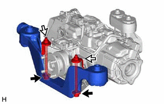
- TEMPORARILY INSTALL REAR NO. 2 DIFFERENTIAL SUPPORT
- Temporarily install the rear No. 2 differential support to the torque vectoring differential carrier assembly with the 2 bolts and 2 nuts.NOTE:
- Reuse the removed bolts and nuts.
- Be sure to install the rear No. 2 differential support facing the direction shown in the illustration.
HINT:
The nuts have tabs to prevent them from rotating.
- Install the 2 rear upper differential mount stoppers to the rear No. 2 differential support.
- Temporarily install the rear No. 2 differential support to the torque vectoring differential carrier assembly with the 2 bolts and 2 nuts.
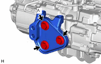
- INSTALL DIFFERENTIAL SUPPORT
- INSTALL REAR NO. 2 DIFFERENTIAL DYNAMIC DAMPER
- Install the rear No. 2 differential dynamic damper and 2 rear upper differential mount stoppers to the differential support with 2 new bolts.
Torque: 12 N.m (122 kgf/cm, 9 ft.lbf)
- Install the rear No. 2 differential dynamic damper and 2 rear upper differential mount stoppers to the differential support with 2 new bolts.
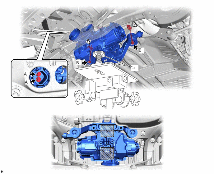
- INSTALL TORQUE VECTORING DIFFERENTIAL CARRIER ASSEMBLY NOTE:
- Do not damage the contact surface when installing the torque vectoring differential carrier assembly.
- Securely support the torque vectoring differential carrier assembly while performing this step to avoid excessively tilting or dropping the torque vectoring differential carrier assembly.
- Install the bolts and nuts with the torque vectoring differential carrier assembly secured.
- Support the torque vectoring differential carrier assembly with a transmission jack using 2 attachments or equivalent tools as shown in the illustration.
- Temporarily install the torque vectoring differential carrier assembly to the rear suspension member sub-assembly with the 2 rear lower differential mount stoppers, 2 new bolts (A), 2 new bolts (B) and 2 new nuts.
*a Attachment - - 
Attachment Installation Position - - - Tighten the 2 bolts (A).
Torque: 130 N.m (1326 kgf/cm, 96 ft.lbf)
NOTE:Do not tighten the bolts with the inner cylinder or rear No. 1 differential mount cushion tilted.
- Tighten the 2 bolts (B).
Torque: 80 N.m (816 kgf/cm, 59 ft.lbf)
NOTE:Do not tighten the bolts with the inner cylinder or rear differential mount cushion tilted.
- Engage the clamp to install the frame wire.
- Connect the 2 connectors and breather tube.
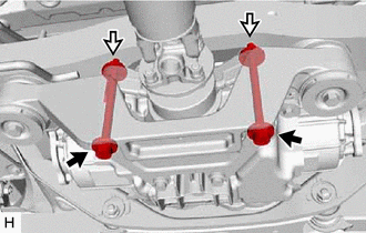
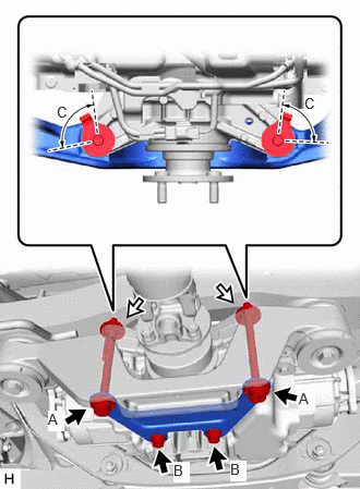
- INSTALL REAR DIFFERENTIAL SUPPORT
Remove the 2 bolts and 2 nuts.
- Temporarily install the rear differential support to the torque vectoring differential carrier assembly with 2 new bolts (A) and 2 new nuts.NOTE:
Be sure to install the tabs of each nut to the positions (C) shown in the illustration.
HINT:
The nuts have tabs to prevent them from rotating.
- Temporarily install 2 new bolts (B).
- Tighten the 4 bolts.
Bolt A
Torque: 82 N.m (836 kgf/cm, 60 ft.lbf)
Bolt B
Torque: 38.5 N.m (393 kgf/cm, 28 ft.lbf)
- INSTALL REAR STABILIZER BAR
Refer to PROCEDURE - Step 4
- INSTALL REAR DRIVE SHAFT ASSEMBLY
- Install the rear drive shaft assembly LH and RH.
Refer to INSTALLATION [12/2019 - 10/2022] , or refer to INSTALLATION [10/2022 - ]
- Install the rear drive shaft assembly LH and RH.
- INSTALL PROPELLER WITH CENTER BEARING SHAFT ASSEMBLY
Refer to INSTALLATION [12/2019 - 10/2022] , or refer to INSTALLATION [10/2022 - ]
- ADD DIFFERENTIAL OIL
Refer to PROCEDURE - Step 4
- INSPECT FOR DIFFERENTIAL OIL LEAK
- DYNAMIC TORQUE VECTORING AWD SYSTEM CALIBRATION
Refer to CALIBRATION [12/2019 - ]