Removal [12/2019 - 10/2022]: Procedure
- PRECAUTION NOTE:
After turning the ignition switch off, waiting time may be required before disconnecting the cable from the negative (-) auxiliary battery terminal. Therefore, make sure to read the disconnecting the cable from the negative (-) auxiliary battery terminal notices before proceeding with work.
- REMOVE BATTERY SERVICE HOLE COVER (for HV Model)
Refer to PROCEDURE - Step 1
- DISCONNECT CABLE FROM NEGATIVE AUXILIARY BATTERY TERMINAL
for 2GR-FKS:
Refer to PROCEDURE - Step 1
for A25A-FXS:
Refer to PROCEDURE - Step 2
- REMOVE REAR BUMPER ASSEMBLY
Refer to REMOVAL [12/2019 - 09/2020] , or refer to REMOVAL [09/2020 - 10/2022]
- REMOVE KICK DOOR CONTROL SENSOR WITH BRACKET
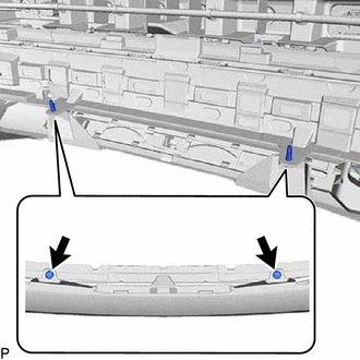
- Remove the 2 clips.
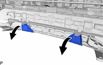
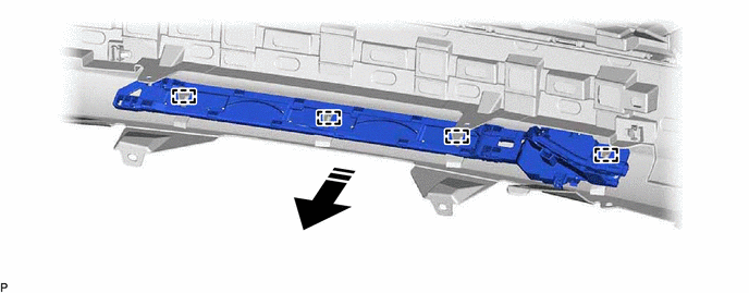
- Separate the rear bumper assembly as shown in the illustration.
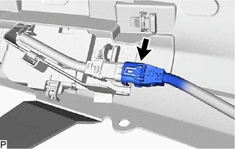
- Disconnect the connector.NOTE:
Do not touch the terminals of the kick door control sensor connector.
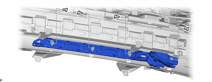
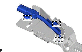
- Remove the 4 clips.
- Disengage the 4 guides to remove the kick door control sensor with bracket as shown in the illustration.

Remove in this Direction - -
- Remove the 2 clips.
- REMOVE KICK DOOR CONTROL SENSOR
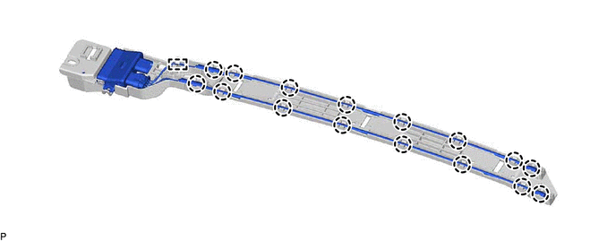
- Disengage the 3 clamps.
- Disengage the 16 claws and guide.
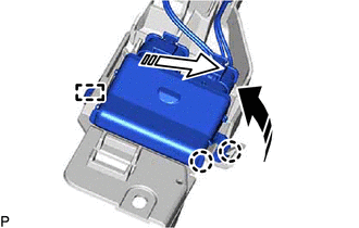
- Disengage the 2 claws and guide to remove the kick door control sensor from the kick door control bracket as shown in the illustration.
Remove in this Direction (1) 
Remove in this Direction (2) NOTE:- Do not subject the kick door control sensor to a strong impact or drop it.
- Do not reuse a kick door control sensor which has been subjected to a strong impact or dropped.
- Be careful not to pull the wire harness.
- Be careful not to twist the wire harness.
- Disengage the 3 clamps.