Removal [10/2022 - 11/2023]: Procedure
- PERFORM ACCUMULATOR PRESSURE ZERO DOWN
- Using the GTS, perform the accumulator pressure zero down operation.
- Select "Motor Deactivate" on the "ECB Utility" screen.
Chassis > Brake/EPB > Utility
Tester Display ECB Utility - Perform "Motor Deactivate" according to the display on the GTS.
- Select "ECB Deactivate" on the "ECB Utility" screen.
Chassis > Brake/EPB > Utility
Tester Display ECB Utility - Perform "ECB Deactivate" according to the display on the GTS.
- Depress the brake pedal 40 times or more to return all the fluid in the accumulator back to the reservoir.
HINT:
A buzzer may sound due to low accumulator pressure. As this is not a malfunction, continue the procedure.
- Check that the brake pedal is firm.NOTE:
If the brake pedal is not firm or the pump motor continues to operate even after depressing the brake pedal 40 times or more, the accumulator pressure zero down operation is not complete.
- Disconnect the cable from the negative (-) auxiliary battery terminal.
Refer to REMOVAL [10/2022 - 11/2023]
- Select "Motor Deactivate" on the "ECB Utility" screen.
- When the accumulator pressure zero down could not be performed using the GTS.NOTE:
If DTCs are output, the accumulator pressure zero down operation may not be complete. In this case, perform the following procedure.
- With the ignition switch off, disconnect the brake master cylinder with pump assembly connector.NOTE:
Be careful not to allow any brake fluid to enter the connector.
- Depress the brake pedal 40 times or more to return all the fluid in the accumulator back to the reservoir.
- Check that the brake pedal is firm.NOTE:
If the brake pedal is not firm or the pump motor continues to operate even after depressing the brake pedal 40 times or more, the accumulator pressure zero down operation is not complete.
- Disconnect the cable from the negative (-) auxiliary battery terminal.
Refer to REMOVAL [10/2022 - 11/2023]
- With the ignition switch off, disconnect the brake master cylinder with pump assembly connector.
- Using the GTS, perform the accumulator pressure zero down operation.
- REMOVE WINDSHIELD WIPER MOTOR AND LINK ASSEMBLY
Refer to REMOVAL [12/2019 - ]
- REMOVE FENDER SPLASH SHIELD SUB-ASSEMBLY REAR LH
Refer to PROCEDURE - Step 3
- REMOVE FENDER SPLASH SHIELD SUB-ASSEMBLY REAR RH
HINT:
Perform the same procedure as for the LH side.
- REMOVE FRONT FENDER SPLASH SHIELD SEAL FRONT LH
Refer to PROCEDURE - Step 5
- REMOVE FRONT FENDER SPLASH SHIELD SEAL FRONT RH
HINT:
Perform the same procedure as for the LH side.
- REMOVE FRONT UPPER SUSPENSION TO COWL BRACE SUB-ASSEMBLY LH
Refer to PROCEDURE - Step 7
- REMOVE FRONT UPPER SUSPENSION TO COWL BRACE SUB-ASSEMBLY RH
HINT:
Perform the same procedure as for the LH side.
- REMOVE COWL VENTILATOR PANEL SUB-ASSEMBLY
Refer to PROCEDURE - Step 9
- REMOVE ECM
Refer to REMOVAL [10/2022 - 11/2023]
- DRAIN BRAKE FLUID NOTE:
If brake fluid leaks onto any painted surface, immediately wash it off.
- DISCONNECT ENGINE ROOM MAIN WIRE
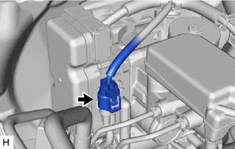
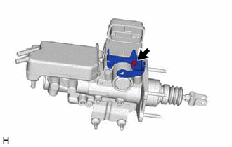
- Disconnect the connector from the brake master cylinder with pump assembly.
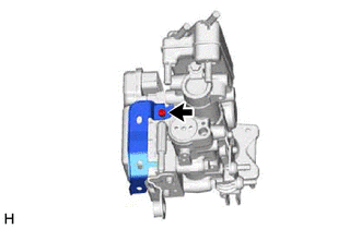
- Release the lock lever and disconnect the connector from the brake master cylinder with pump assembly.

Release the lock lever 
Disconnect the connector NOTE:Be careful not to allow any brake fluid to enter the connector.
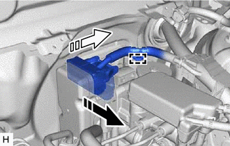
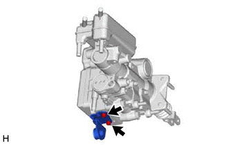
- Disengage the clamp to separate the engine room main wire from the brake master cylinder with pump assembly.
- Remove the bolt to separate the engine room main wire from the vehicle body.
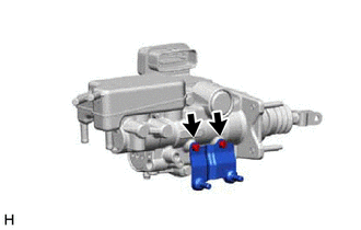
- Disconnect the connector from the brake master cylinder with pump assembly.
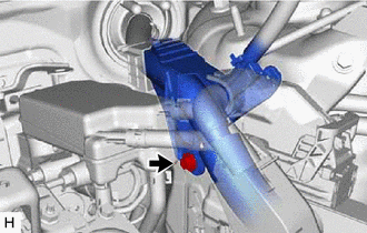
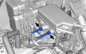
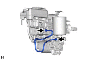
- DISCONNECT RESERVOIR HOSE
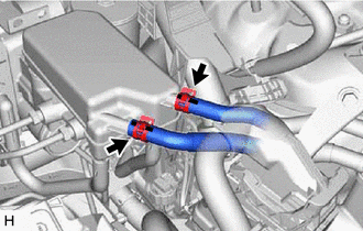
- DISCONNECT BRAKE LINE
- REMOVE FRONT DOOR SCUFF PLATE LH
Refer to PROCEDURE - Step 9
- REMOVE COWL SIDE TRIM SUB-ASSEMBLY LH
Refer to PROCEDURE - Step 3
- REMOVE NO. 1 INSTRUMENT PANEL UNDER COVER SUB-ASSEMBLY
Refer to PROCEDURE - Step 17
- DISCONNECT HOOD LOCK CONTROL LEVER SUB-ASSEMBLY
Refer to PROCEDURE - Step 18
- REMOVE LOWER INSTRUMENT PANEL FINISH PANEL SUB-ASSEMBLY
Refer to PROCEDURE - Step 19
- REMOVE NO. 1 SWITCH HOLE BASE
Refer to PROCEDURE - Step 20
- REMOVE LOWER NO. 1 INSTRUMENT PANEL AIRBAG ASSEMBLY
Refer to PROCEDURE - Step 10
- REMOVE VEHICLE APPROACHING SPEAKER CONTROLLER
Refer to PROCEDURE - Step 2
- REMOVE STOP LIGHT SWITCH ASSEMBLY
Refer to PROCEDURE - Step 4
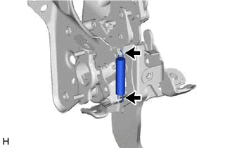
- REMOVE BRAKE PEDAL RETURN SPRING
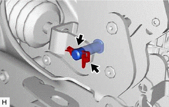
- REMOVE PUSH ROD PIN
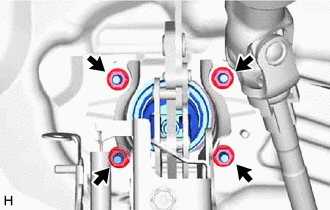
- REMOVE BRAKE MASTER CYLINDER WITH PUMP ASSEMBLY
- REMOVE BRAKE BOOSTER GASKET
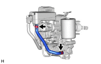
- REMOVE NO. 2 RESERVOIR HOSE
- REMOVE NO. 1 RESERVOIR HOSE
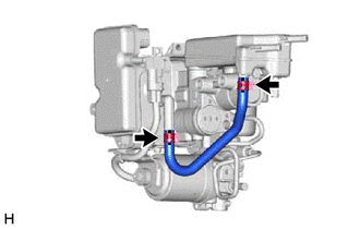
- REMOVE NO. 1 BRAKE ACTUATOR TUBE
- REMOVE BRAKE BOOSTER WITH ACCUMULATOR PUMP ASSEMBLY
See step 3
- REMOVE NO. 1 WIRE CLAMP BRACKET
- REMOVE NO. 2 WIRE CLAMP BRACKET
- REMOVE NO. 3 BRAKE POWER SUPPLY BRACKET
- REMOVE NO. 2 BRAKE POWER SUPPLY BRACKET