Installation [12/2019 - 10/2022]: Procedure
- INSTALL WATER INLET WITH THERMOSTAT SUB-ASSEMBLY
- Install a new gasket to the water inlet with thermostat sub-assembly.
- Install the water inlet with thermostat sub-assembly with the 2 bolts and 2 nuts.
Torque: 10 N.m (102 kgf/cm, 7 ft.lbf)
- CONNECT WATER BY-PASS HOSE
- Connect the water by-pass hose and slide the clip to secure it.
- INSTALL FRONT NO. 1 ENGINE MOUNTING BRACKET LH
Refer to PROCEDURE - Step 76
- INSTALL REAR ENGINE MOUNTING STAY RH
Refer to PROCEDURE - Step 8
- CONNECT ENGINE WIRE
- Engage the clamp to connect the engine wire.
- Install the bolt.
Torque: 10 N.m (102 kgf/cm, 7 ft.lbf)
- Connect the water inlet with thermostat sub-assembly connector.
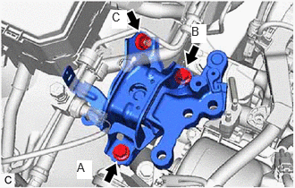
- INSTALL ENGINE MOUNTING INSULATOR SUB-ASSEMBLY RH
- Install the engine mounting insulator sub-assembly RH to the engine mounting spacer and vehicle body with the nut and 2 bolts.
Torque: 72 N.m (734 kgf/cm, 53 ft.lbf)
NOTE:Temporarily tighten the bolt (A), and then fully tighten the 2 bolts and nut in the order of (B), (A) and (C).
- Install the engine mounting insulator sub-assembly RH to the front No. 1 engine mounting bracket LH with the 3 bolts and nut.
Bolt
Torque: 72 N.m (734 kgf/cm, 53 ft.lbf)
Nut
Torque: 42 N.m (428 kgf/cm, 31 ft.lbf)
- Connect the No. 2 earth wire to the engine mounting insulator sub-assembly RH with the bolt.
Torque: 10 N.m (102 kgf/cm, 7 ft.lbf)
- Install the suction hose sub-assembly, suction pipe sub-assembly and air conditioning tube and accessory assembly with the 2 clamps.
- Connect the connector.
- Install the engine mounting insulator sub-assembly RH to the engine mounting spacer and vehicle body with the nut and 2 bolts.
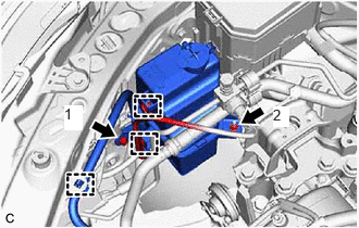
- INSTALL RADIATOR RESERVE TANK ASSEMBLY
- Install the radiator reserve tank assembly with the bolt and nut in the order shown in the illustration.
 Courtesy of © TOYOTA, LICENSE AGREEMENT TMS1002
Torque: 5.0 N.m (51 kgf/cm, 44 in.lbf)
- Engage the 3 clamps
- Install the radiator reserve tank assembly with the bolt and nut in the order shown in the illustration.
- INSTALL NO. 2 ENGINE MOUNTING STAY RH
Refer to PROCEDURE - Step 9
- INSTALL V-BANK COVER SUB-ASSEMBLY
Refer to PROCEDURE - Step 52 [12/2019 - 09/2020] , or refer to PROCEDURE - Step 52 [09/2020 - 10/2022]
- ADD ENGINE COOLANT
Refer to PROCEDURE - Step 2
- INSPECT FOR COOLANT LEAK
Refer to PROCEDURE - Step 3
- INSTALL REAR ENGINE UNDER COVER RH
Refer to PROCEDURE - Step 78 [12/2019 - 09/2020] , or refer to PROCEDURE - Step 78 [09/2020 - 10/2022]
- INSTALL REAR ENGINE UNDER COVER LH
Refer to PROCEDURE - Step 79 [12/2019 - 09/2020] , or refer to PROCEDURE - Step 79 [09/2020 - 10/2022]
- INSTALL NO. 1 ENGINE UNDER COVER
Refer to PROCEDURE - Step 80 [12/2019 - 09/2020] , or refer to PROCEDURE - Step 80 [09/2020 - 10/2022]
- INSTALL FRONT WHEEL OPENING EXTENSION PAD LH
Refer to PROCEDURE - Step 81 [12/2019 - 09/2020] , or refer to PROCEDURE - Step 81 [09/2020 - 10/2022]
- INSTALL FRONT WHEEL OPENING EXTENSION PAD RH
Refer to PROCEDURE - Step 82 [12/2019 - 09/2020] , or refer to PROCEDURE - Step 82 [09/2020 - 10/2022]