Reassembly [12/2019 - 10/2022]: Procedure
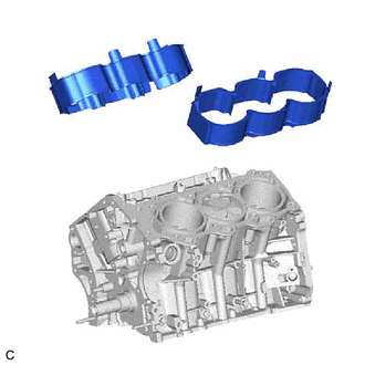
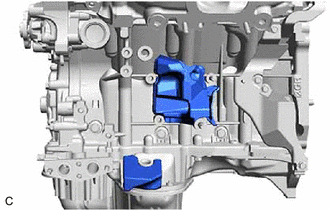
- INSTALL CYLINDER BLOCK WATER JACKET SPACER
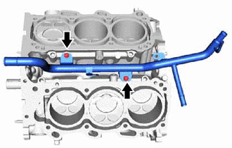
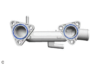
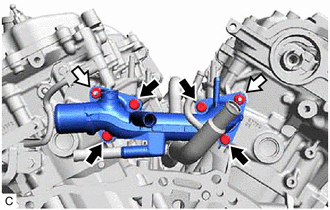
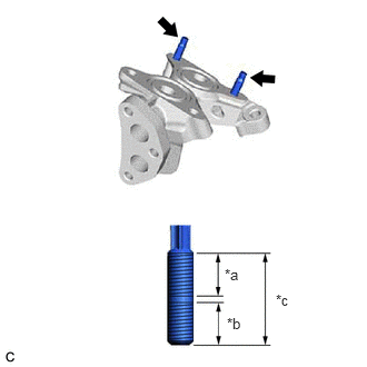
- INSTALL WATER INLET PIPE
- INSTALL NO. 2 CYLINDER HEAD GASKET
Refer to PROCEDURE - Step 1
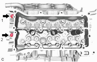
- INSTALL CYLINDER HEAD LH
- Place the cylinder head LH onto the cylinder block sub-assembly.NOTE:
- Do not allow oil to adhere to the bottom of the cylinder head LH.
- Gently lower the cylinder head LH in order not to damage the No. 2 cylinder head gasket with the bottom of the cylinder head LH.
HINT:
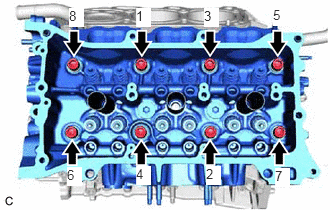
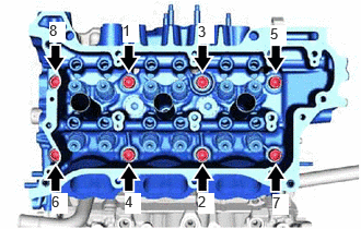
The cylinder head set bolts are tightened in 3 progressive steps.
- Apply a light coat of engine oil to the threads and under the heads of the cylinder head set bolts.
- Step 1:
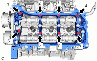
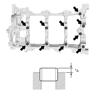
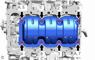
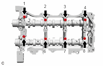
- Using a 10 mm bi-hexagon socket wrench, install and uniformly tighten the 8 cylinder head set bolts with 8 cylinder head set plate washers in several steps in the order shown in the illustration.
Torque: 36 N.m (367 kgf/cm, 27 ft.lbf)
- Using a 10 mm bi-hexagon socket wrench, install and uniformly tighten the 8 cylinder head set bolts with 8 cylinder head set plate washers in several steps in the order shown in the illustration.
- Step 2:
- Step 3:
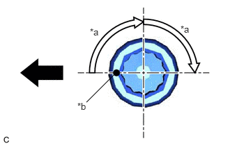
- Tighten the cylinder head set bolts an additional 90° in the order shown in step 1.
- Check that the paint marks are now facing rearward.
- Tighten the 2 bolts in the order shown in the illustration.
Torque: 30 N.m (306 kgf/cm, 22 ft.lbf)
HINT:
Perform Inspection After Repair after replacing the cylinder head LH.
Refer to INITIALIZATION [12/2019 - 10/2022]
- Place the cylinder head LH onto the cylinder block sub-assembly.
- INSTALL CYLINDER HEAD GASKET
Refer to PROCEDURE - Step 3
- INSTALL CYLINDER HEAD SUB-ASSEMBLY
- Place the cylinder head sub-assembly onto the cylinder block sub-assembly.NOTE:
- Do not allow oil to adhere to the bottom of the cylinder head sub-assembly.
- Gently lower the cylinder head sub-assembly in order not to damage the cylinder head gasket with the bottom of the cylinder head sub-assembly.
HINT:
The cylinder head set bolts are tightened in 3 progressive steps.
- Apply a light coat of engine oil to the threads and under the heads of the cylinder head set bolts.
- Step 1:
- Using a 10 mm bi-hexagon socket wrench, install and uniformly tighten the 8 cylinder head set bolts with 8 cylinder head set plate washers in several steps in the order shown in the illustration.
Torque: 36 N.m (367 kgf/cm, 27 ft.lbf)
- Using a 10 mm bi-hexagon socket wrench, install and uniformly tighten the 8 cylinder head set bolts with 8 cylinder head set plate washers in several steps in the order shown in the illustration.
- Step 2:
- Step 3:
- Tighten the cylinder head set bolts an additional 90° in the order shown in step 1.
- Check that the paint marks are now facing rearward.
HINT:
Perform Inspection After Repair after replacing the cylinder head sub-assembly.
Refer to INITIALIZATION [12/2019 - 10/2022]
- Place the cylinder head sub-assembly onto the cylinder block sub-assembly.
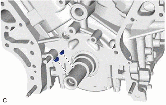
- INSTALL REAR ENGINE OIL SEAL
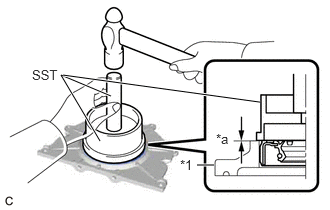
- Place the rear engine oil seal retainer on wooden blocks.
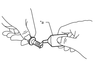
- Apply MP grease to the lip of a new rear engine oil seal.
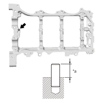
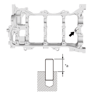
- Using SST and a hammer, tap in the rear engine oil seal.
*1 Rear Engine Oil Seal Retainer *a Oil Seal Protrusion Height - SST: 09223-15030
- SST: 09950-70010
- 09951-07100
Oil Seal Protrusion Height
-0.5 to 0.5 mm (-0.0197 to 0.0197 in.)
NOTE:- Keep the lip free from foreign matter.
- Do not tap in the rear engine oil seal at an angle.
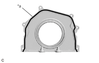
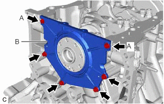
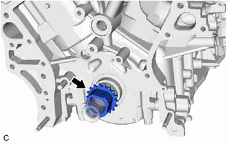
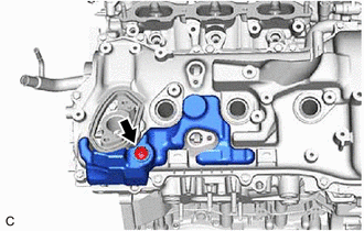
- INSTALL REAR ENGINE OIL SEAL RETAINER
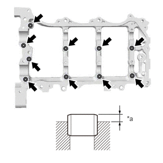
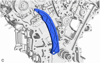
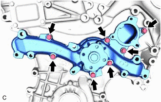
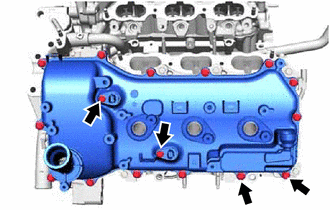
- Apply seal packing in a continuous line as shown in the illustration.
*a Seal Packing Seal Packing
Toyota Genuine Seal Packing Black, Three Bond 1207B or equivalent
Seal Packing Diameter
2.0 to 3.0 mm (0.0787 to 0.118 in.)
NOTE:- Remove any oil from the contact surfaces.
- Install the rear engine oil seal retainer within 3 minutes of applying seal packing.
- Do not start the engine for at least 2 hours after installation.
- Install the rear engine oil seal retainer to the cylinder block sub-assembly with the 6 bolts.
Torque: 10 N.m (102 kgf/cm, 7 ft.lbf)
Adhesive
Toyota Genuine Adhesive 1324, Three Bond 1324 or equivalent
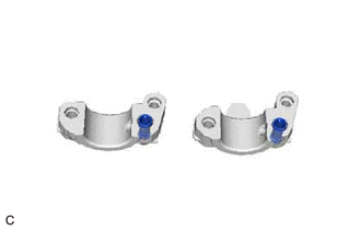
NOTE:- Be sure to apply adhesive to the bolts (A) before installing them.
- Wipe off any seal packing that seeped out from the crankshaft position sensor insert part (B).
- Apply seal packing in a continuous line as shown in the illustration.
- INSTALL SENSOR WIRE
- INSTALL VALVE STEM CAP
- INSTALL VALVE LASH ADJUSTER ASSEMBLY
- Inspect the valve lash adjuster assembly.
See step 2
- Install the 24 valve lash adjuster assemblies to the cylinder head sub-assembly and cylinder head LH.NOTE:
Install each part to its original position.
- Inspect the valve lash adjuster assembly.
- INSTALL NO. 1 VALVE ROCKER ARM SUB-ASSEMBLY
- Apply engine oil to the valve lash adjuster assembly tip and valve stem cap end.
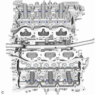
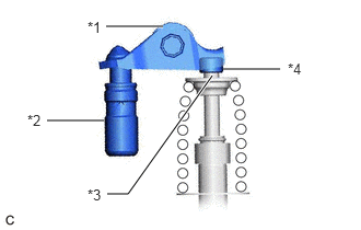
- Install the 24 No. 1 valve rocker arm sub-assemblies as shown in the illustration.
*1 No. 1 Valve Rocker Arm Sub-assembly *2 Valve Lash Adjuster Assembly *3 Valve Stem *4 Valve Stem Cap NOTE:Install each part to its original position.
- INSTALL STRAIGHT PIN (for Bank 2)
HINT:
It is not necessary to remove the straight pin unless it is being replaced.
- INSTALL CAMSHAFT BEARING CAP SETTING RING PIN (for Bank 2)
HINT:
It is not necessary to remove the camshaft bearing cap setting ring pins unless they are being replaced.
- INSTALL NO. 3 CAMSHAFT SUB-ASSEMBLY
- Apply a light coat of engine oil to the No. 3 camshaft sub-assembly journals and camshaft housing sub-assembly LH.
- Install the No. 3 camshaft sub-assembly to the camshaft housing sub-assembly LH.
HINT:
Perform Inspection After Repair after replacing the No. 3 camshaft sub-assembly.
Refer to INITIALIZATION [12/2019 - 10/2022]
- INSTALL NO. 4 CAMSHAFT SUB-ASSEMBLY
- Apply a light coat of engine oil to the No. 4 camshaft sub-assembly journals and camshaft housing sub-assembly LH.
- Install the No. 4 camshaft sub-assembly to the camshaft housing sub-assembly LH.
HINT:
Perform Inspection After Repair after replacing the No. 4 camshaft sub-assembly.
Refer to INITIALIZATION [12/2019 - 10/2022]
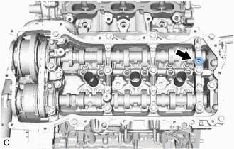
- INSTALL CAMSHAFT BEARING CAP (for Bank 2)
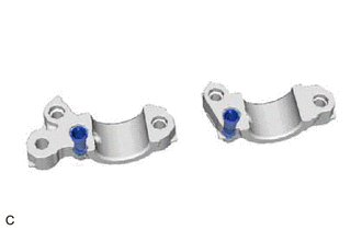
- Install the 2 oil control valve filters to the 2 camshaft bearing caps.
- Apply engine oil to the 5 camshaft bearing caps.
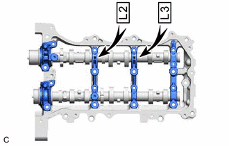
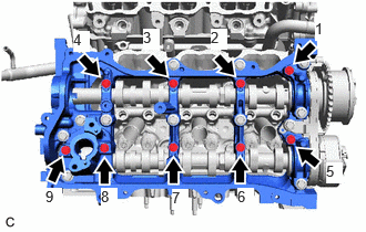
- Install the 5 camshaft bearing caps to the camshaft housing sub-assembly LH.
- Temporarily install and tighten the 8 bolts in the order shown in the illustration.
 Courtesy of © TOYOTA, LICENSE AGREEMENT TMS1002
Torque: 10 N.m (102 kgf/cm, 7 ft.lbf)
- Install the 2 oil control valve filters to the 2 camshaft bearing caps.
- INSTALL NO. 3 CHAIN TENSIONER ASSEMBLY
- SET CAMSHAFT TIMING GEAR ASSEMBLY, CAMSHAFT TIMING EXHAUST GEAR ASSEMBLY AND NO. 2 CHAIN SUB-ASSEMBLY (for Bank 2)
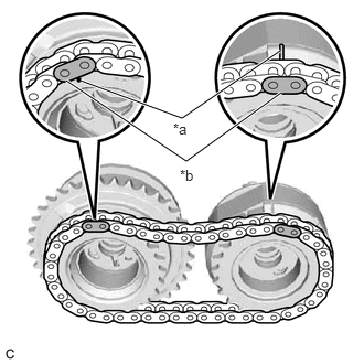
- Align the mark plates (yellow) with the timing marks of the camshaft timing gear assembly and camshaft timing exhaust gear assembly as shown in the illustration.
*a Timing Mark *b Mark Plate - Align the straight pins of the No. 3 camshaft sub-assembly and No. 4 camshaft sub-assembly with the pin holes of the camshaft timing gear assembly and camshaft timing exhaust gear assembly. Temporarily install the camshaft timing gear assembly and camshaft timing exhaust gear assembly with the No. 2 chain sub-assembly installed.NOTE:
Be careful not to damage the contact surface of the camshaft timing gear assembly and camshaft timing exhaust gear assembly with the straight pins of the No. 3 camshaft sub-assembly and No. 4 camshaft sub-assembly.
HINT:
Perform Inspection After Repair after replacing the camshaft timing gear assembly or camshaft timing exhaust gear assembly.
Refer to INITIALIZATION [12/2019 - 10/2022]
- Align the mark plates (yellow) with the timing marks of the camshaft timing gear assembly and camshaft timing exhaust gear assembly as shown in the illustration.
- TEMPORARILY INSTALL CAMSHAFT TIMING GEAR BOLT (for Intake Side of Bank 2)
Refer to PROCEDURE - Step 8
- TEMPORARILY INSTALL CAMSHAFT TIMING GEAR BOLT (for Exhaust Side of Bank 2)
Refer to PROCEDURE - Step 9
- INSTALL CAMSHAFT HOUSING SUB-ASSEMBLY LH
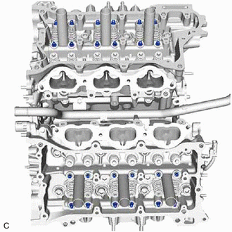
- Make sure that the No. 1 valve rocker arm sub-assemblies are installed as shown in the illustration.
*1 No. 1 Valve Rocker Arm Sub-assembly *2 Valve Lash Adjuster Assembly *3 Valve Stem *4 Valve Stem Cap - Apply seal packing as shown in the illustration.
Seal Packing
Toyota Genuine Seal Packing Black, Three Bond 1207B or equivalent
Seal Packing Application Specification
Area Seal Packing Diameter Continuous Line Area 3.0 to 4.0 mm (0.118 to 0.157 in.) Dashed Line Area 4.0 to 4.5 mm (0.157 to 0.177 in.) NOTE:- Remove any oil from the contact surface.
- Install the camshaft housing sub-assembly LH within 3 minutes and tighten the bolts within 15 minutes of applying seal packing.
- Do not add engine oil for at least 2 hours after installation.
- Do not start the engine for at least 2 hours after installation.
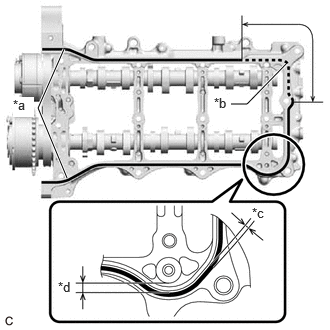
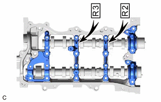
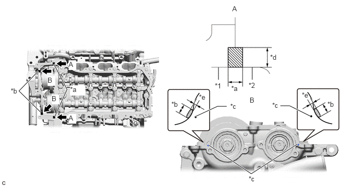
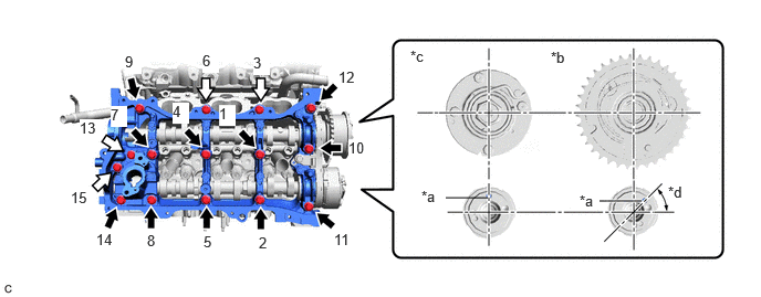
*a Continuous Line Area *b Dashed Line Area *c 3.0 to 4.0 mm *d Separated by 4.0 to 6.0 mm (0.157 to 0.236 in.) - Install the camshaft housing sub-assembly LH with the 15 bolts in the order shown in the illustration.
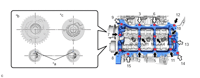 Courtesy of © TOYOTA, LICENSE AGREEMENT TMS1002
*a Straight Pin *b Intake Side *c Exhaust Side - - 
Bolt (A) 
Bolt (B) Torque: 28 N.m (286 kgf/cm, 21 ft.lbf)
Bolt Length
Item Length Bolt (A) 68 mm (2.68 in.) Bolt (B) 48 mm (1.89 in.) NOTE:- When installing the camshaft housing sub-assembly LH, correctly position the camshafts as shown in the illustration. Failure to do so may result in damage due to contact between the pistons and valves. If a camshaft is rotated, valve contact with a piston at TDC may occur.
- Make sure that the No. 1 valve rocker arm sub-assemblies are correctly installed.
- If it is necessary to loosen any of the bolts during installation, remove the camshaft housing sub-assembly LH, clean the installation surfaces, and reapply seal packing.
- If it is necessary to remove the camshaft housing sub-assembly LH during installation, make sure that the previously applied seal packing does not enter any oil passages.
- Tighten the 8 bolts in the order shown in the illustration.
Torque: 16 N.m (163 kgf/cm, 12 ft.lbf)
- Remove any protruding seal packing black.NOTE:
Be careful not to drop seal packing black into the cylinder head LH.
- Make sure that the No. 1 valve rocker arm sub-assemblies are installed as shown in the illustration.
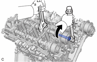
- TIGHTEN CAMSHAFT TIMING GEAR BOLT (for Intake Side of Bank 2)
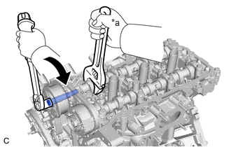
- Using a wrench to hold the hexagonal portion of the No. 3 camshaft sub-assembly, tighten the camshaft timing gear bolt of the camshaft timing gear assembly.
Torque: 95 N.m (969 kgf/cm, 70 ft.lbf)
*a Hold Turn NOTE:Be careful not to damage the No. 3 camshaft sub-assembly, camshaft housing sub-assembly LH or spark plug tube with the wrench.
- Using a wrench to hold the hexagonal portion of the No. 3 camshaft sub-assembly, tighten the camshaft timing gear bolt of the camshaft timing gear assembly.
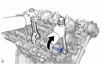
- TIGHTEN CAMSHAFT TIMING GEAR BOLT (for Exhaust Side of Bank 2)
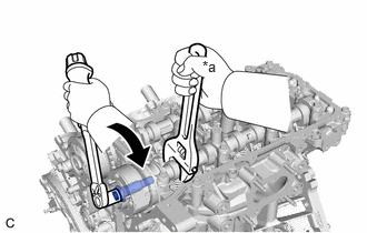
- Using a wrench to hold the hexagonal portion of the No. 4 camshaft sub-assembly, tighten the camshaft timing gear bolt of the camshaft timing exhaust gear assembly.
Torque: 95 N.m (969 kgf/cm, 70 ft.lbf)
NOTE:Be careful not to damage the No. 4 camshaft sub-assembly, camshaft housing sub-assembly LH or spark plug tube with the wrench.
*a Hold Turn - Remove the pin from the No. 3 chain tensioner assembly.
- Using a wrench to hold the hexagonal portion of the No. 4 camshaft sub-assembly, tighten the camshaft timing gear bolt of the camshaft timing exhaust gear assembly.
- INSTALL STRAIGHT PIN (for Bank 1)
HINT:
It is not necessary to remove the straight pin unless it is being replaced.
- INSTALL CAMSHAFT BEARING CAP SETTING RING PIN (for Bank 1)
HINT:
It is not necessary to remove the camshaft bearing cap setting ring pins unless they are being replaced.
- INSTALL CAMSHAFT
- Apply a light coat of engine oil to the camshaft journals and camshaft housing sub-assembly.
- Install the camshaft to the camshaft housing sub-assembly.
HINT:
Perform Inspection After Repair after replacing the camshaft.
Refer to INITIALIZATION [12/2019 - 10/2022]
- INSTALL NO. 2 CAMSHAFT
- Apply a light coat of engine oil to the No. 2 camshaft journals and camshaft housing sub-assembly.
- Install the No. 2 camshaft to the camshaft housing sub-assembly.
HINT:
Perform Inspection After Repair after replacing the No. 2 camshaft.
Refer to INITIALIZATION [12/2019 - 10/2022]
- INSTALL CAMSHAFT BEARING CAP (for Bank 1)
- Install the 2 oil control valve filters to the 2 camshaft bearing caps.
- Apply engine oil to the 5 camshaft bearing caps.
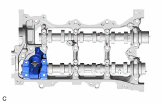
- Install the 5 camshaft bearing caps to the camshaft housing sub-assembly.
- Install the fuel pump lifter housing to the camshaft housing sub-assembly.
- Temporarily install and tighten the 9 bolts in the order shown in the illustration.
Torque: 10 N.m (102 kgf/cm, 7 ft.lbf)
Bolt Length
Item Length Bolt (A) 40 mm (1.57 in.) Bolt (B) 58 mm (2.28 in.) 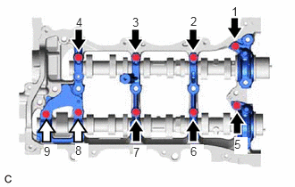 Courtesy of © TOYOTA, LICENSE AGREEMENT TMS1002
Bolt (A) Bolt (B)
- Install the 2 oil control valve filters to the 2 camshaft bearing caps.
- INSTALL NO. 2 CHAIN TENSIONER ASSEMBLY
- SET CAMSHAFT TIMING GEAR ASSEMBLY, CAMSHAFT TIMING EXHAUST GEAR ASSEMBLY AND NO. 2 CHAIN SUB-ASSEMBLY (for Bank 1)
- Align the mark plates (yellow) with the timing marks of the camshaft timing gear assembly and camshaft timing exhaust gear assembly as shown in the illustration.
*a Timing Mark *b Mark Plate - Align the straight pins of the camshaft and No. 2 camshaft with the pin holes of the camshaft timing gear assembly and camshaft timing exhaust gear assembly. Temporarily install the camshaft timing gear assembly and camshaft timing exhaust gear assembly with the No. 2 chain sub-assembly installed.NOTE:
Be careful not to damage the contact surface of the camshaft timing gear assembly and camshaft timing exhaust gear assembly with the straight pins of the camshaft and No. 2 camshaft.
HINT:
Perform Inspection After Repair after replacing the camshaft timing gear assembly or camshaft timing exhaust gear assembly.
Refer to INITIALIZATION [12/2019 - 10/2022]
- Align the mark plates (yellow) with the timing marks of the camshaft timing gear assembly and camshaft timing exhaust gear assembly as shown in the illustration.
- TEMPORARILY INSTALL CAMSHAFT TIMING GEAR BOLT (for Intake Side of Bank 1)
Refer to PROCEDURE - Step 21
- TEMPORARILY INSTALL CAMSHAFT TIMING GEAR BOLT (for Exhaust Side of Bank 1)
See step 33
- INSTALL CAMSHAFT HOUSING SUB-ASSEMBLY
- Make sure that the No. 1 valve rocker arm sub-assemblies are installed as shown in the illustration.
*1 No. 1 Valve Rocker Arm Sub-assembly *2 Valve Lash Adjuster Assembly *3 Valve Stem *4 Valve Stem Cap - Apply seal packing as shown in the illustration.
Seal Packing
Toyota Genuine Seal Packing Black, Three Bond 1207B or equivalent
Seal Packing Diameter
3.0 to 4.0 mm (0.118 to 0.157 in.)
NOTE:- Remove any oil from the contact surface.
- Install the camshaft housing sub-assembly within 3 minutes and tighten the bolts within 15 minutes of applying seal packing.
- Do not add engine oil for at least 2 hours after installation.
- Do not start the engine for at least 2 hours after installation.
*a Seal Packing *b 3.0 to 4.0 mm *c Separated by 4.0 to 6.0 mm (0.157 to 0.236 in.) - Install the camshaft housing sub-assembly with the 15 bolts in the order shown in the illustration.
 Courtesy of © TOYOTA, LICENSE AGREEMENT TMS1002
*a Straight Pin *b Intake Side *c Exhaust Side *d 45° Bolt (A) Bolt (B) Torque: 28 N.m (286 kgf/cm, 21 ft.lbf)
Bolt Length
Item Length Bolt (A) 68 mm (2.68 in.) Bolt (B) 48 mm (1.89 in.) NOTE:- When installing the camshaft housing sub-assembly, correctly position the camshafts as shown in the illustration. Failure to do so may result in damage due to contact between the pistons and valves. If a camshaft is rotated, valve contact with a piston at TDC may occur.
- Make sure that the No. 1 valve rocker arm sub-assemblies are correctly installed.
- If it is necessary to loosen any of the bolts during installation, remove the camshaft housing sub-assembly, clean the installation surfaces, and reapply seal packing.
- If it is necessary to remove the camshaft housing sub-assembly during installation, make sure that the previously applied seal packing does not enter any oil passages.
- Tighten the 9 bolts in the order shown in the illustration.
Torque: 16 N.m (163 kgf/cm, 12 ft.lbf)
- Remove any protruding seal packing black.NOTE:
Be careful not to drop seal packing black into the cylinder head sub-assembly.
- Make sure that the No. 1 valve rocker arm sub-assemblies are installed as shown in the illustration.
- TIGHTEN CAMSHAFT TIMING GEAR BOLT (for Intake Side of Bank 1)
- TIGHTEN CAMSHAFT TIMING GEAR BOLT (for Exhaust Side of Bank 1)
- Using a wrench to hold the hexagonal portion of No. 2 camshaft, tighten the camshaft timing gear bolt of the camshaft timing exhaust gear assembly.
Torque: 95 N.m (969 kgf/cm, 70 ft.lbf)
NOTE:Be careful not to damage the No. 2 camshaft, camshaft housing sub-assembly or spark plug tube with the wrench.
*a Hold Turn - Remove the pin from the No. 2 chain tensioner assembly.
- Using a wrench to hold the hexagonal portion of No. 2 camshaft, tighten the camshaft timing gear bolt of the camshaft timing exhaust gear assembly.
- INSTALL CRANKSHAFT TIMING GEAR KEY
- INSTALL CRANKSHAFT TIMING SPROCKET
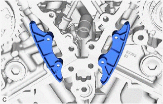
- INSTALL NO. 2 CHAIN VIBRATION DAMPER
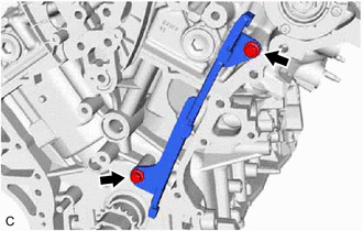
- INSTALL NO. 1 CHAIN VIBRATION DAMPER
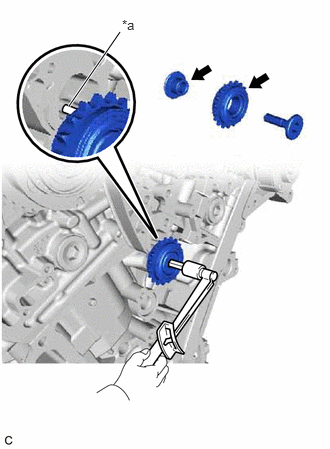
- INSTALL IDLE SPROCKET ASSEMBLY
- Apply a light coat of engine oil to the rotating surface of the No. 1 idle gear shaft.
*a Knock Pin Light coat of engine oil - Temporarily install the No. 1 idle gear shaft and idle sprocket assembly with the No. 2 idle gear shaft while aligning the knock pin of the No. 1 idle gear shaft with the pin hole of the cylinder block sub-assembly.NOTE:
Make sure to install the No. 1 idle gear shaft installation in the correct direction.
HINT:
Check that there is no foreign matter on the No. 1 idle gear shaft or No. 2 idle gear shaft.
- Using a 10 mm hexagon socket wrench, tighten the No. 2 idle gear shaft.
Torque: 60 N.m (612 kgf/cm, 44 ft.lbf)
HINT:
After installing the idle sprocket assembly, check that the idle sprocket assembly turns smoothly.
- Apply a light coat of engine oil to the rotating surface of the No. 1 idle gear shaft.
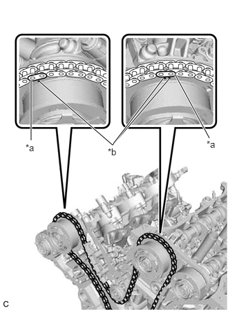
- INSTALL CHAIN SUB-ASSEMBLY
- Align the mark plates and timing marks as shown in the illustration and install the chain sub-assembly.
*a Mark Plate *b Timing Mark HINT:
The camshaft mark plates are yellow.
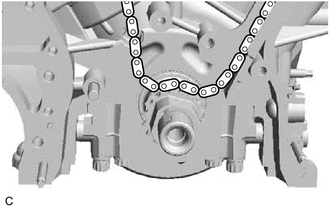
- Temporarily place the chain sub-assembly on the crankshaft as shown in the illustration.
- Turn the camshaft timing gear assembly on bank 1 counterclockwise to tighten the chain sub-assembly between the banks.
*a Chain Plate *b When the idle sprocket assembly is reused *c Mark *d Align Turn NOTE:When reusing the idle sprocket assembly, align the chain plate with the mark where the mark plate had been in order to tighten the chain sub-assembly between the banks.
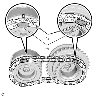
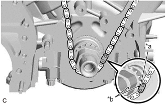
- Align the mark plate and timing marks as shown in the illustration and install the chain sub-assembly around the crankshaft timing sprocket.
*a Mark Plate *b Timing Mark HINT:
The crankshaft mark plate is pink.
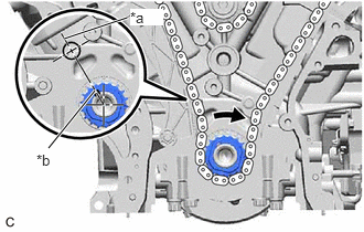
- Temporarily tighten the crankshaft pulley set bolt to the crankshaft.
- Turn the crankshaft clockwise to set it to the center line of the block bore (for Bank 1) (TDC /compression).
*a Center Line *b Key Groove
- Align the mark plates and timing marks as shown in the illustration and install the chain sub-assembly.
- INSTALL CHAIN TENSIONER SLIPPER
- INSTALL NO. 1 CHAIN TENSIONER ASSEMBLY
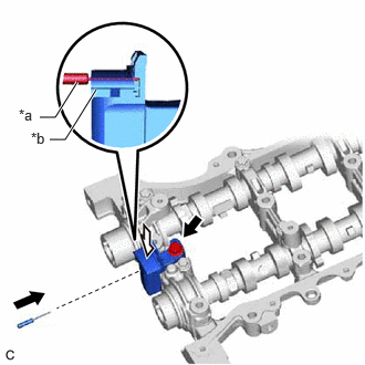
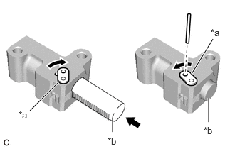
- Turn the stopper plate clockwise to release the lock, and push the plunger deep into the No. 1 chain tensioner assembly.
*a Stopper Plate *b Plunger - Turn the stopper plate counterclockwise to set the lock, and insert a 1.0 mm (0.0394 in.) diameter pin into the hole of the stopper plate.
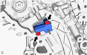
- Install the No. 1 chain tensioner assembly with the 2 bolts.
Torque: 10 N.m (102 kgf/cm, 7 ft.lbf)
- Remove the 1.0 mm (0.0394 in.) diameter pin from the No. 1 chain tensioner assembly.
- Turn the stopper plate clockwise to release the lock, and push the plunger deep into the No. 1 chain tensioner assembly.
- INSPECT VALVE TIMING
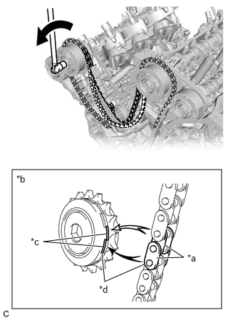
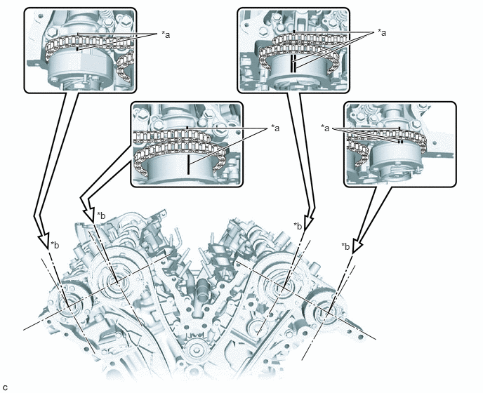
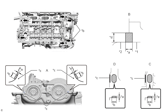
- Check the camshaft timing marks.NOTE:
- Check each timing mark from a viewpoint directly in line with the center of the camshaft and the timing mark on each camshaft timing gear assembly and each camshaft timing exhaust gear assembly.
- If the timing marks are checked from any other viewpoint, the valve timing may appear misaligned.
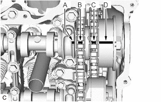
- Check that each camshaft timing mark is positioned as shown in the illustration.
*a Timing Mark *b Viewpoint HINT:
For the camshaft or No. 3 camshaft sub-assembly:
Be sure to check the mark (A) at the point where the marks (B), (C) and (D) are positioned in line. If the marks are checked from any other viewpoint, they cannot be checked correctly.
- If the valve timing is misaligned, reinstall the chain sub-assembly.
- Remove the crankshaft pulley set bolt from the crankshaft.
- Check the camshaft timing marks.
- INSTALL ENGINE WATER PUMP ASSEMBLY
- INSTALL TIMING CHAIN COVER ASSEMBLY
Refer to PROCEDURE - Step 1
- INSTALL TIMING CHAIN CASE OIL SEAL
Refer to PROCEDURE - Step 1
- INSTALL TIMING CHAIN COVER PLATE
- INSTALL NO. 1 OIL PAN BAFFLE PLATE
- INSTALL OIL FILTER BRACKET CLIP
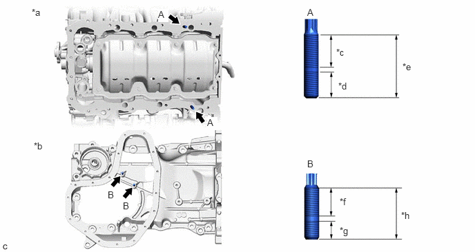
- INSTALL OIL PAN SUB-ASSEMBLY NOTE:
If a stud bolt is deformed or its threads are damaged, replace it.
- Using an E8 and E6 "TORX" socket wrench, install the 4 stud bolts to the oil pan sub-assembly and cylinder block sub-assembly.
*a Cylinder Block Sub-assembly Side *b Oil Pan Sub-assembly Side *c 20 mm (0.787 in.) *d 13 mm (0.512 in.) *e 35 mm (1.38 in.) *f 16 mm (0.630 in.) *g 9 mm (0.354 in.) *h 27 mm (1.06 in.) Stud bolt (A)
Torque: 10 N.m (102 kgf/cm, 7 ft.lbf)
Stud bolt (B)
Torque: 4.0 N.m (41 kgf/cm, 35 in.lbf)
- Using an E8 "TORX" socket wrench, install the 2 stud bolts to the oil pan sub-assembly.
Torque: 10 N.m (102 kgf/cm, 7 ft.lbf)
*a 20 mm (0.787 in.) *b 13 mm (0.512 in.) *c 35 mm (1.38 in.) - Install the oil pan sub-assembly.
Refer to PROCEDURE - Step 38
- Using an E8 and E6 "TORX" socket wrench, install the 4 stud bolts to the oil pan sub-assembly and cylinder block sub-assembly.
- INSTALL ENGINE OIL LEVEL SENSOR
Refer to PROCEDURE - Step 1
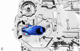
- INSTALL OIL STRAINER SUB-ASSEMBLY
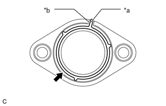
- Apply a light coat of engine oil to a new oil strainer gasket.
- Align the protrusion of the oil strainer gasket with the cutout of the oil strainer sub-assembly, and install the oil strainer gasket to the oil strainer sub-assembly.
*a Protrusion *b Cutout - Install the oil strainer sub-assembly to the timing chain cover assembly with the 2 nuts.
Torque: 10 N.m (102 kgf/cm, 7 ft.lbf)
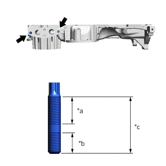
- INSTALL NO. 2 OIL PAN SUB-ASSEMBLY NOTE:
If a stud bolt is deformed or its threads are damaged, replace it.
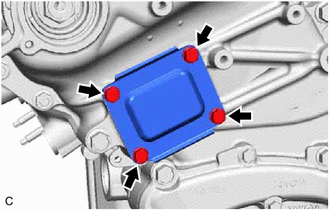
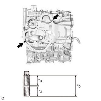
- Using an E6 "TORX" socket wrench, install the 2 stud bolts to the oil pan sub-assembly as shown in the illustration.
*a 9 mm (0.354 in.) *b 19 mm (0.748 in.) Torque: 4.0 N.m (41 kgf/cm, 35 in.lbf)
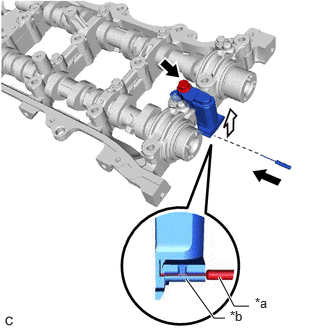
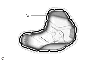
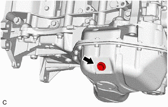
- Apply seal packing in a continuous line as shown in the illustration.
*a Seal Packing Seal Packing
Toyota Genuine Seal Packing Black, Three Bond 1207B or equivalent
Seal Packing Diameter
3.0 to 4.0 mm (0.118 to 0.157 in.)
NOTE:- Remove any oil from the contact surfaces.
- Install the No. 2 oil pan sub-assembly within 3 minutes of applying seal packing.
- Do not start the engine for at least 2 hours after installation.
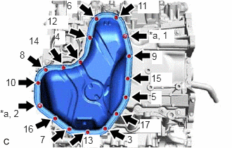
- Install the No. 2 oil pan sub-assembly with the 15 bolts and 2 nuts as shown in the illustration.
Torque: 10 N.m (102 kgf/cm, 7 ft.lbf)
*a Nut
- Using an E6 "TORX" socket wrench, install the 2 stud bolts to the oil pan sub-assembly as shown in the illustration.
- INSTALL ENGINE OIL PRESSURE SWITCH ASSEMBLY
Refer to PROCEDURE - Step 1
- INSTALL OIL FILTER CAP ASSEMBLY
Refer to PROCEDURE - Step 4 [12/2019 - 09/2020] , or refer to PROCEDURE - Step 4 [09/2020 - 10/2021] , or refer to PROCEDURE - Step 4 [10/2021 - 10/2022]
- INSTALL OIL PAN DRAIN PLUG
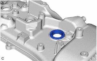
- INSTALL SPARK PLUG TUBE GASKET
- INSTALL CYLINDER HEAD COVER SUB-ASSEMBLY LH
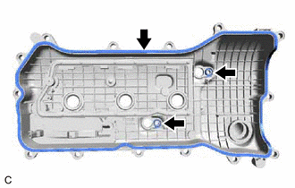
- Install 3 new No. 2 cylinder head cover gaskets to the cylinder head cover sub-assembly LH.NOTE:
Make sure that there is no oil or foreign matter inside the groove of the camshaft housing sub-assembly LH or on the contact surfaces of the cylinder head cover sub-assembly LH and timing chain cover assembly. Clean if necessary.
- Install a new camshaft bearing cap oil hole gasket LH to the camshaft bearing cap.
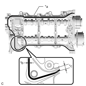
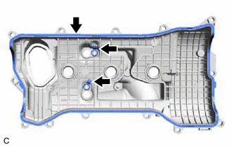
- Apply seal packing as shown in the illustration.
*1 Timing Chain Cover Assembly *2 Camshaft Housing Sub-assembly LH *a Seal Packing (Diameter 2.0 to 3.0 mm (0.0787 to 0.118 in.)) *b Seal Packing (Diameter 5.0 to 7.0 mm (0.197 to 0.276 in.)) *c Mark *d 5.0 to 10 mm (0.197 to 0.394 in.) *e Thickness: 1.0 to 3.0 mm (0.0394 to 0.118 in.) - - Seal Packing - - Seal Packing
Toyota Genuine Seal Packing Black, Three Bond 1207B or equivalent
NOTE:- Remove any oil from the contact surfaces.
- Install the cylinder head cover sub-assembly LH within 3 minutes and tighten the bolts within 15 minutes of applying seal packing.
- Do not start the engine for at least 2 hours after installation.
- Apply a light coat of engine oil to the 2 O-rings of the 2 VVT sensors (for Exhaust Side of Bank 2 and for Intake Side of Bank 2).NOTE:
If reusing the 2 VVT sensors (for Exhaust Side of Bank 2 and for Intake Side of Bank 2), be sure to inspect them before installation.
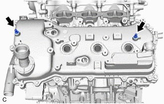
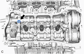
- Clean the 4 bolt holes and bolts shown in the illustration.
- Apply adhesive to 2 to 3 threads at the end of each bolt that was cleaned in the previous step.
*a Adhesive Adhesive
Toyota Genuine Adhesive 1324, Three Bond 1324 or equivalent
- Install the cylinder head cover sub-assembly LH with the 16 bolts and 2 VVT sensors (for Exhaust Side of Bank 2 and for Intake Side of Bank 2) in the order shown in the illustration.
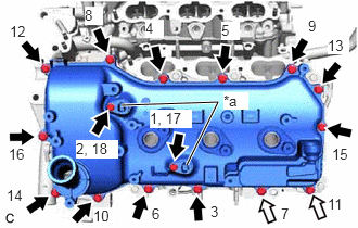 Courtesy of © TOYOTA, LICENSE AGREEMENT TMS1002
*a Bolt with VVT Sensor Bolt (A) Bolt (B) Bolt (A)
Torque: 10 N.m (102 kgf/cm, 7 ft.lbf)
Bolt (B)
Torque: 7.3 N.m (74 kgf/cm, 65 in.lbf)
NOTE:- If a VVT sensor (for Exhaust Side of Bank 2 or for Intake Side of Bank 2) has been struck or dropped, replace it.
- Make sure that the 2 O-rings are not cracked or moved out of place when installing the 2 VVT sensors (for Exhaust Side of Bank 2 and for Intake Side of Bank 2).
HINT:
After tightening all bolts, check the tightening torque of the bolts (1) and (18). Retighten them if necessary.
Install the 2 No. 1 V-bank cover brackets to the cylinder head cover sub-assembly LH.
Torque: 10 N.m (102 kgf/cm, 7 ft.lbf)
- Install 3 new No. 2 cylinder head cover gaskets to the cylinder head cover sub-assembly LH.
- INSTALL CYLINDER HEAD COVER SUB-ASSEMBLY
- Install 3 new cylinder head cover gaskets to the cylinder head cover sub-assembly.NOTE:
Make sure that there is no oil or foreign matter inside the groove of the camshaft housing sub-assembly or on the contact surfaces of the cylinder head cover sub-assembly and timing chain cover assembly. Clean if necessary.
- Install a new camshaft bearing cap oil hole gasket to the camshaft bearing cap.
- Apply seal packing as shown in the illustration.
*1 Timing Chain Cover Assembly *2 Camshaft Housing Sub-assembly *a Seal Packing (Diameter 2.0 to 3.0 mm (0.0787 to 0.118 in.)) *b Seal Packing (Diameter 5.0 to 7.0 mm (0.197 to 0.276 in.)) *c Mark *d 5.0 to 10 mm (0.197 to 0.394 in.) *e Thickness: 1.0 to 3.0 mm (0.0394 to 0.118 in.) - - Seal Packing - - Seal Packing
Toyota Genuine Seal Packing Black, Three Bond 1207B or equivalent
NOTE:- Remove any oil from the contact surfaces.
- Install the cylinder head cover sub-assembly within 3 minutes and tighten the bolts within 15 minutes of applying seal packing.
- Do not start the engine for at least 2 hours after installation.
- Apply a light coat of engine oil to the 2 O-rings of the 2 VVT sensors (for Exhaust Side of Bank 1 and for Intake Side of Bank 1).NOTE:
If reusing the 2 VVT sensors (for Exhaust Side of Bank 1 and for Intake Side of Bank 1), be sure to inspect them before installation.
- Clean the 2 bolts and 2 bolt holes of the VVT sensors (for Exhaust Side of Bank 1 and for Intake Side of Bank 1).
- Apply adhesive to 2 or 3 threads at the end of the 2 bolts of the VVT sensors (for Exhaust Side of Bank 1 and for Intake Side of Bank 1).
*a Adhesive Adhesive
Toyota Genuine Adhesive 1324, Three Bond 1324 or equivalent
- Install the cylinder head cover sub-assembly with the 15 bolts and 2 VVT sensors (for Exhaust Side of Bank 1 and for Intake Side of Bank 1) in the order shown in the illustration.
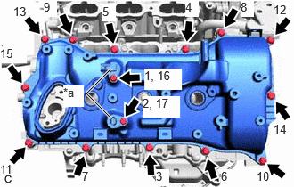 Courtesy of © TOYOTA, LICENSE AGREEMENT TMS1002
*a Bolt with VVT Sensor Torque: 10 N.m (102 kgf/cm, 7 ft.lbf)
NOTE:- If a VVT sensor (for Exhaust Side of Bank 1 or for Intake Side of Bank 1) has been struck or dropped, replace it.
- Make sure that the 2 O-rings are not cracked or moved out of place when installing the 2 VVT sensors (for Exhaust Side of Bank 1 and for Intake Side of Bank 1).
HINT:
After tightening all bolts, check the tightening torque of the bolts (1) and (17). Retighten them if necessary.
- Install the No. 1 engine cover sub-assembly to the cylinder head cover sub-assembly with the clip.
- Install 3 new cylinder head cover gaskets to the cylinder head cover sub-assembly.
- INSTALL WATER OUTLET
- Install 2 new No. 2 water inlet housing gaskets to the water outlet.
- w/ Stud Bolt:
Bolt Bolt or Nut - Install the water outlet to the cylinder head sub-assembly and cylinder head LH with the 4 bolts and 2 nuts.
Torque: 10 N.m (102 kgf/cm, 7 ft.lbf)
- Install the water outlet to the cylinder head sub-assembly and cylinder head LH with the 4 bolts and 2 nuts.
- w/o Stud Bolt:
- Install the water outlet to the cylinder head sub-assembly and cylinder head LH with the 6 bolts.
Torque: 10 N.m (102 kgf/cm, 7 ft.lbf)
- Install the water outlet to the cylinder head sub-assembly and cylinder head LH with the 6 bolts.
- Install 2 new No. 2 water inlet housing gaskets to the water outlet.
- INSTALL ENGINE COOLANT TEMPERATURE SENSOR
Refer to PROCEDURE - Step 1
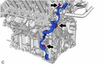
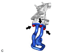
- INSTALL OIL COOLER PIPE NOTE:
If a stud bolt is deformed or its threads are damaged, replace it.
- Install the No. 2 cylinder block insulator and No. 3 cylinder block insulator to the cylinder block sub-assembly and oil pan sub-assembly.
- Using an E8 "TORX" socket wrench, install the 2 stud bolts to the No. 1 oil cooler bracket as shown in the illustration.
*a 14 mm (0.551 in.) *b 13 mm (0.512 in.) *c 29 mm (1.14 in.) Torque: 10 N.m (102 kgf/cm, 7 ft.lbf)
- Install the oil cooler pipe and a new oil cooler gasket to the No. 1 oil cooler bracket with the 3 bolts.
Torque: 21 N.m (214 kgf/cm, 15 ft.lbf)
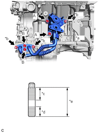
- Using an E7 "TORX" socket wrench, install the stud bolt to the cylinder block sub-assembly as shown in the illustration.
*a Stud Bolt *b Nut *c 22 mm (0.866 in.) *d 12 mm (0.472 in.) *e 39 mm (1.54 in.) Torque: 10 N.m (102 kgf/cm, 7 ft.lbf)
- Install a new oil hole cover gasket to the oil pan sub-assembly.
- Install the No. 1 oil cooler bracket with oil cooler pipe with the 4 bolts and 3 nuts.
Torque: 21 N.m (214 kgf/cm, 15 ft.lbf)
Bolt Length
Item Length Bolt (A) 30 mm (1.18 in.) Bolt (B) 20 mm (0.787 in.)
- Install the No. 2 cylinder block insulator and No. 3 cylinder block insulator to the cylinder block sub-assembly and oil pan sub-assembly.
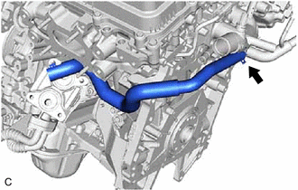
- INSTALL NO. 5 WATER BY-PASS HOSE
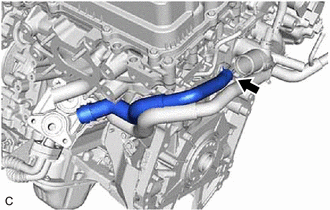
- INSTALL NO. 4 WATER BY-PASS HOSE
- INSTALL OIL COOLER ASSEMBLY
Refer to PROCEDURE - Step 1
- INSTALL CRANKSHAFT POSITION SENSOR
Refer to PROCEDURE - Step 1
- INSTALL CRANKSHAFT POSITION SENSOR PROTECTOR
Refer to PROCEDURE - Step 2
- INSTALL CAMSHAFT TIMING OIL CONTROL SOLENOID ASSEMBLY (for Intake Side of Bank 2)
Refer to PROCEDURE - Step 1
- INSTALL CAMSHAFT TIMING OIL CONTROL SOLENOID ASSEMBLY (for Exhaust Side of Bank 2)
Refer to PROCEDURE - Step 6
- INSTALL CAMSHAFT TIMING OIL CONTROL SOLENOID ASSEMBLY (for Exhaust Side of Bank 1)
Refer to PROCEDURE - Step 3
- INSTALL CAMSHAFT TIMING OIL CONTROL SOLENOID ASSEMBLY (for Intake Side of Bank 1)
Refer to PROCEDURE - Step 5
- INSTALL WATER INLET WITH THERMOSTAT SUB-ASSEMBLY
Refer to PROCEDURE - Step 1
- INSTALL WATER BY-PASS HOSE
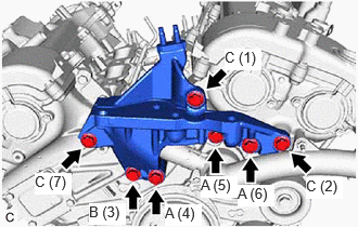
- INSTALL FRONT NO. 1 ENGINE MOUNTING BRACKET LH NOTE:
If a stud bolt is deformed or its threads are damaged, replace it.
- Using an E8 "TORX" socket wrench, install the 2 stud bolts to the front No. 1 engine mounting bracket LH.
Torque: 10 N.m (102 kgf/cm, 7 ft.lbf)
*a 14 mm (0.551 in.) *b 13 mm (0.512 in.) *c 29 mm (1.14 in.) - Install the front No. 1 engine mounting bracket LH to the timing chain cover assembly with the 7 bolts in the order shown in the illustration.
Torque: 54 N.m (551 kgf/cm, 40 ft.lbf)
 Courtesy of © TOYOTA, LICENSE AGREEMENT TMS1002
Bolt Length
Item Length Bolt (A) 115 mm (4.53 in.) Bolt (B) 85 mm (3.35 in.) Bolt (C) 40 mm (1.57 in.) NOTE:Make sure that there is no oil on the threads of the bolts.
- Using an E8 "TORX" socket wrench, install the 2 stud bolts to the front No. 1 engine mounting bracket LH.
- INSTALL CRANKSHAFT PULLEY
Refer to PROCEDURE - Step 2
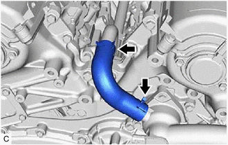
- INSTALL CYLINDER BLOCK WATER DRAIN COCK SUB-ASSEMBLY
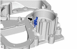
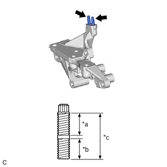
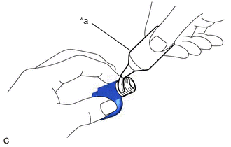
- Apply adhesive to the cylinder block water drain cock sub-assembly.
*a Adhesive Adhesive
Toyota Genuine Adhesive 1324, Three Bond 1324 or equivalent
NOTE:Install the cylinder block water drain cock sub-assembly within 3 minutes of applying adhesive.
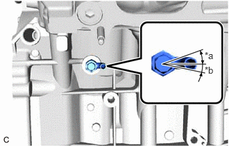
- Install the cylinder block water drain cock sub-assembly to the cylinder block sub-assembly as shown in the illustration.
*a 20° *b 12° Torque: 25 N.m (255 kgf/cm, 18 ft.lbf)
NOTE:- Do not rotate the cylinder block water drain cock sub-assembly more than 1 revolution (360°) after tightening it to the specified torque.
- Do not loosen the cylinder block water drain cock sub-assembly after setting it to the correct position.
- Install the cylinder block water drain cock plug to the cylinder block water drain cock sub-assembly.
Torque: 12.7 N.m (130 kgf/cm, 9 ft.lbf)
- Apply adhesive to the cylinder block water drain cock sub-assembly.
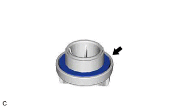
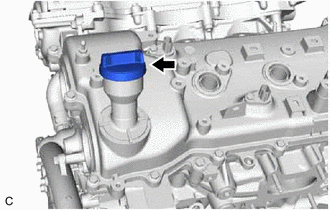
- INSTALL PCV VALVE (VENTILATION VALVE SUB-ASSEMBLY)
Refer to PROCEDURE - Step 1
- INSTALL SPARK PLUG
Refer to PROCEDURE - Step 1
- INSTALL OIL FILLER CAP SUB-ASSEMBLY