Removal [10/2022 - 11/2023]: Procedure
- REMOVE SERVICE PLUG GRIP (for HV Model)
Refer to REMOVAL [10/2022 - 11/2023]
- CHECK TERMINAL VOLTAGE (for HV Model)
- Remove the No. 2 inverter protector.
Refer to PROCEDURE - Step 9
- Disconnect the engine room main wire.
Refer to PROCEDURE - Step 10
- Remove the connector cover assembly.
Refer to PROCEDURE - Step 11
- Check the terminal voltage.
Refer to PROCEDURE - Step 12
- Install the connector cover assembly.
Refer to PROCEDURE - Step 7
- Connect the engine room main wire.
Refer to PROCEDURE - Step 16
- Install the No. 2 inverter protector.
Refer to PROCEDURE - Step 17
- Remove the No. 2 inverter protector.
- REMOVE REAR NO. 2 SEAT ASSEMBLY
Refer to REMOVAL [12/2019 - ]
- REMOVE VOLTAGE INVERTER ASSEMBLY (for Gasoline Model)
- REMOVE INVERTER UPPER COVER (for HV Model)
- REMOVE VOLTAGE INVERTER ASSEMBLY WITH BRACKET (for HV Model)
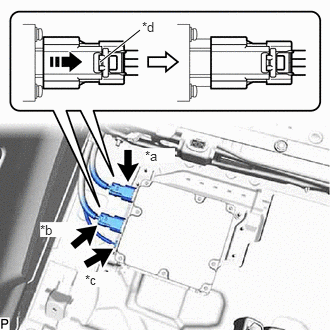
- Using a screwdriver, slide the green-colored lock of the connector (A) and (B) as shown in the illustration to release it and disconnect the 2 connectors.
*a Connector (A) *b Connector (B) *c Connector (C) *d Green-colored Lock 
Slide WARNING:Make sure to wear insulated gloves.
NOTE:Insulate the disconnected terminals and connector with insulating tape.
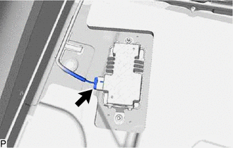
- Disconnect the connector (C).
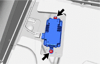
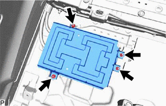
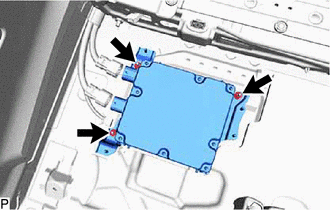
- Remove the 3 nuts and voltage inverter assembly with bracket.
- Using a screwdriver, slide the green-colored lock of the connector (A) and (B) as shown in the illustration to release it and disconnect the 2 connectors.
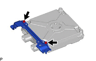
- REMOVE VOLTAGE INVERTER BRACKET (for HV Model)
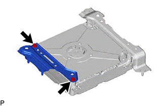
- REMOVE NO. 2 VOLTAGE INVERTER BRACKET (for HV Model)
- REMOVE VOLTAGE INVERTER ASSEMBLY (for HV Model)