Removal [10/2022 - 11/2023]: Procedure
- PRECAUTION
Refer to PRECAUTION [12/2019 - 11/2023]
- REMOVE SERVICE PLUG GRIP
Refer to REMOVAL [10/2022 - 11/2023]
- REMOVE NO. 2 INVERTER PROTECTOR
See step 9
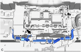
- DISCONNECT ENGINE ROOM MAIN WIRE
Refer to PROCEDURE - Step 4
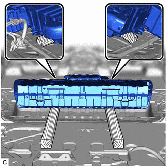
- REMOVE CONNECTOR COVER ASSEMBLY
See step 11
- CHECK TERMINAL VOLTAGE
See step 12
- INSTALL CONNECTOR COVER ASSEMBLY WARNING:
Be sure to wear insulated gloves.
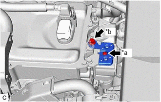
- Using a T25 "TORX" socket wrench, install the connector cover assembly to the inverter with converter assembly with the bolt (A).
Torque: 4.5 N.m (46 kgf/cm, 40 in.lbf)
*a Bolt (A) *b Bolt (B) NOTE:- Do not touch the connector cover assembly waterproof seal.
- Do not allow any foreign matter or water to enter the inverter with converter assembly.
- Install the bolt (B).
Torque: 8.0 N.m (82 kgf/cm, 71 in.lbf)
- Using a T25 "TORX" socket wrench, install the connector cover assembly to the inverter with converter assembly with the bolt (A).
- CONNECT ENGINE ROOM MAIN WIRE
Refer to PROCEDURE - Step 31
- INSTALL NO. 2 INVERTER PROTECTOR
See step 17
- REMOVE BATTERY COOLING BLOWER ASSEMBLY
Refer to REMOVAL [12/2019 - ]
- REMOVE NO. 3 FLOOR BOARD
- REMOVE NO. 2 FLOOR BOARD
- REMOVE NO. 1 FLOOR BOARD
- REMOVE REAR NO. 2 SEAT ASSEMBLY
Refer to REMOVAL [12/2019 - ]
- REMOVE FRONT DECK SIDE TRIM COVER LH
Refer to PROCEDURE - Step 31
- REMOVE FRONT DECK SIDE TRIM COVER RH
Refer to PROCEDURE - Step 41
- REMOVE CENTER PROTECTOR COVER
- REMOVE REAR SEAT SUB FLOOR PANEL ASSEMBLY
- REMOVE VOLTAGE INVERTER ASSEMBLY (w/ Voltage Inverter)
Refer to REMOVAL [10/2022 - 11/2023]
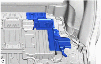
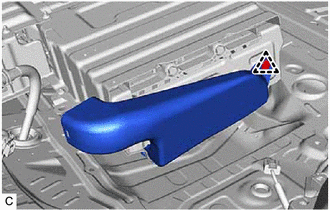
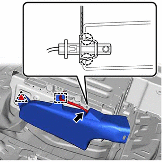
- REMOVE NO. 10 HV BATTERY SHIELD PANEL WARNING:
Be sure to wear insulated gloves.
- for Captain Seat Type:
- Remove the 2 nuts and No. 3 console box mounting bracket from the HV battery.
*1 No. 3 Console Box Mounting Bracket *2 No. 4 Console Box Mounting Bracket - Remove the 2 nuts and No. 4 console box mounting bracket from the HV battery.
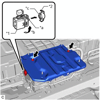
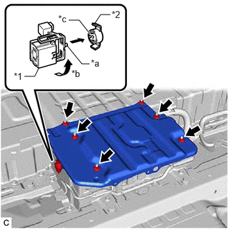
- Using the service plug grip, remove the battery cover lock striker.
*1 Service Plug Grip *2 Battery Cover Lock Striker *a Projection *b Turn *c Button HINT:
Insert the projection of the service plug grip and turn the button of the battery cover lock striker counterclockwise to release the lock.
- Remove the 2 nuts and No. 10 HV battery shield panel from the HV battery.
- Remove the 2 nuts and No. 3 console box mounting bracket from the HV battery.
- for 60/40 Split Seat Type:
- Using the service plug grip, remove the battery cover lock striker.
*1 Service Plug Grip *2 Battery Cover Lock Striker *a Projection *b Turn *c Button HINT:
Insert the projection of the service plug grip and turn the button of the battery cover lock striker counterclockwise to release the lock.
- Remove the 6 nuts and No. 10 HV battery shield panel from the HV battery.
- Using the service plug grip, remove the battery cover lock striker.
- for Captain Seat Type:
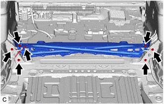
- DISCONNECT FLOOR UNDER WIRE WARNING:
Be sure to wear insulated gloves.
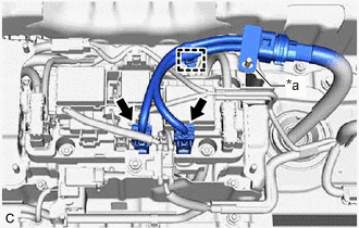
- Disconnect the 2 HV battery junction block assembly connectors.
*a Shield Ground NOTE:Insulate each disconnected high-voltage connector with insulating tape. Wrap the connector from the wire harness side to the end of the connector.
- Disengage the clamp.
- Disconnect the shield ground from the HV battery.
- Disconnect the 2 HV battery junction block assembly connectors.
- DISCONNECT FLOOR WIRE WARNING:
Be sure to wear insulated gloves.
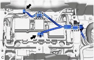
- Disengage the 2 clamps.
- Disconnect the floor wire connector.
- Disconnect the HV battery junction block assembly connector.
- w/ 1500w Voltage Inverter
- Disconnect the 2 HV battery junction block assembly connectors.NOTE:
Insulate each disconnected high-voltage connector with insulating tape. Wrap the connector from the wire harness side to the end of the connector.
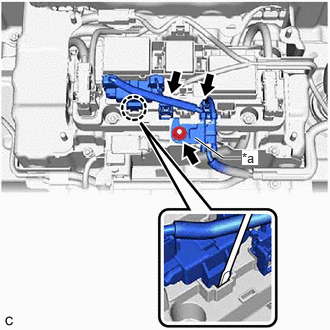
*a Shield Ground - Using a screwdriver disengage the claw.
- Remove the nut and disconnect the shield ground.
- Disconnect the 2 HV battery junction block assembly connectors.
- Disconnect the electric vehicle battery plug assembly connector.
- Disengage the 3 clamps to disconnect the floor wire.
- Disengage the 2 clamps.
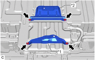
- INSTALL NO. 10 HV BATTERY SHIELD PANEL
See step 6
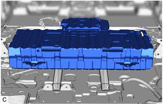
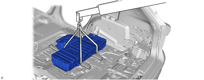
- REMOVE HV BATTERY WARNING:
Be sure to wear insulated gloves.
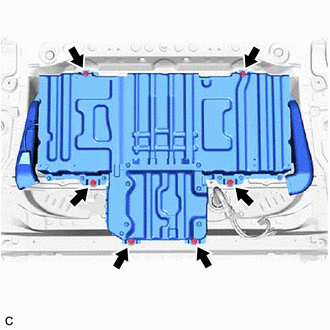
- Remove the 6 bolts.NOTE:
- Do not allow foreign matter, such as grease or oil, to adhere to the bolts of the HV battery.
- To prevent the wire harness from being caught, make sure to bundle the wire harness using insulating tape or equivalent.
- Use cardboard or another similar material to protect the HV battery and vehicle body from damage.
- Since the HV battery is very heavy, 2 people are needed to remove it. When removing the HV battery, be careful not to damage the parts around it.
- When removing the HV battery from the vehicle, do not allow it to contact the vehicle.
- When removing/installing/moving the HV battery, make sure not to tilt it more than 80°.
- Insulate the disconnected terminals or connectors with insulating tape.
- If the HV battery has been struck or dropped, replace it.
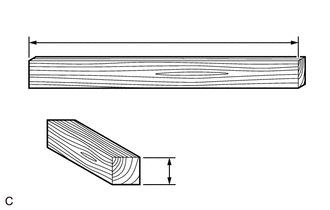
- Prepare wooden blocks that will be used to pull out the HV battery.
Wooden block 45 mm (1.7717 in.) x 45 mm (1.7717 in.) x 1000 mm (3.28 ft.) HINT:
The wooden blocks dimensions are an approximation.
- Tilt the HV battery and place wooden blocks.
- Set the wooden blocks as shown in the illustration.
- Remove the clip and No. 2 HV battery intake duct LH from the HV battery.
- Disengage the clamp.
- Using a screwdriver with its tip wrapped with protective tape, disengage the 2 claws and disconnect the HV battery thermistor from the No. 2 HV battery intake duct RH.NOTE:
- Be careful not to damage the HV battery thermistor.
- When disconnecting the HV battery thermistor, hold it gently and pull it straight out.
- Remove the clip and No. 2 HV battery intake duct RH from the HV battery.
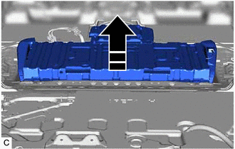
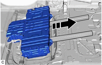
- Pull the HV battery to the rear of the vehicle as shown in the illustration.
- Pull the HV battery to the rear of the vehicle at the positions shown in the illustration.
- Using a suitable adaptor such as straps, remove the HV battery while tilting it.
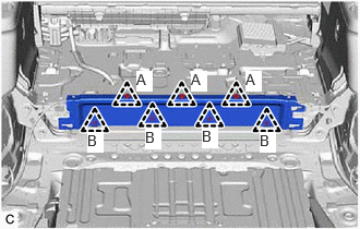
- Remove the 6 bolts.
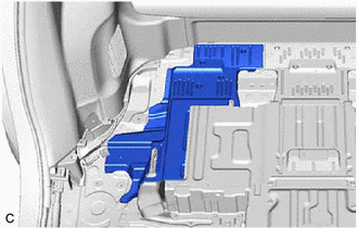
- REMOVE NO. 10 HV BATTERY SHIELD PANEL
- Remove the 6 nuts and No. 10 HV battery shield panel from the HV battery.
- REMOVE HV BATTERY JUNCTION BLOCK ASSEMBLY
Refer to PROCEDURE - Step 19
- REMOVE NO. 1 HYBRID BATTERY SHIELD SUB-ASSEMBLY
Refer to PROCEDURE - Step 19
- REMOVE HYBRID BATTERY TERMINAL BLOCK
Refer to PROCEDURE - Step 20
- REMOVE NO. 6 HV BATTERY CARRIER BRACKET
See step 4
- REMOVE BATTERY VOLTAGE SENSOR
See step 5