Replacement [10/2022 - 11/2023]: Procedure
- DISABLE BRAKE CONTROL (for HV Model)
Refer to PROCEDURE - Step 1
- REMOVE FRONT WHEEL
Refer to PROCEDURE - Step 1
- SEPARATE FRONT FLEXIBLE HOSE
- SEPARATE FRONT DISC BRAKE CALIPER ASSEMBLY
- Remove the 2 bolts and separate the front disc brake caliper assembly from the steering knuckle.NOTE:
Use wire or an equivalent tool to keep the front disc brake caliper assembly from hanging by the front flexible hose.
- Remove the 2 bolts and separate the front disc brake caliper assembly from the steering knuckle.
- REMOVE FRONT DISC
Refer to PROCEDURE - Step 12
- REMOVE FRONT AXLE HUB BOLT
- Temporarily install 2 service nuts to the front axle hub bolts as shown in the illustration.
*a Service Nut Recommended Service Nut
Thread diameter: 12.0 mm (0.472 in.)
Thread pitch: 1.5 mm (0.0591 in.)
NOTE:Install the service nuts to prevent damage to the front axle hub bolts.
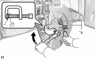
- Using SST and a screwdriver or an equivalent tool to hold the front axle hub sub-assembly, remove the front axle hub bolt.
- SST: 09611-12010
NOTE:Do not damage the threads of the front axle hub bolts.
- Temporarily install 2 service nuts to the front axle hub bolts as shown in the illustration.
- INSTALL FRONT AXLE HUB BOLT
- Temporarily install a new front axle hub bolt to the front axle hub sub-assembly.
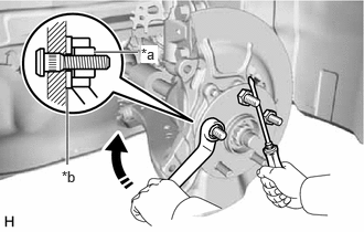
- Install a washer and service nut to the front axle hub bolt as shown in the illustration.
*a Service Nut *b Washer Recommended Service Nut
Thread diameter: 12.0 mm (0.472 in.)
Thread pitch: 1.5 mm (0.0591 in.)
HINT:
Recommended washer thickness is 5 mm (0.197 in.) or more.
- Using a screwdriver or an equivalent tool to hold the front axle hub sub-assembly, install the front axle hub bolt by tightening the service nut.NOTE:
- Install the service nuts to prevent damage to the front axle hub bolts.
- Do not damage the threads of the front axle hub bolts.
- Remove the 3 service nuts and washer from the 3 front axle hub bolts.
- INSTALL FRONT DISC
Refer to PROCEDURE - Step 1
- INSTALL FRONT DISC BRAKE CALIPER ASSEMBLY
- Install the front disc brake caliper assembly to the steering knuckle with the 2 bolts.
Torque: 192 N.m (1958 kgf/cm, 142 ft.lbf)
NOTE:- Do not twist the front flexible hose when installing the front disc brake caliper assembly.
- Make sure that there is no foreign matter on the threads of the bolt.
- Install the front disc brake caliper assembly to the steering knuckle with the 2 bolts.
- INSTALL FRONT FLEXIBLE HOSE
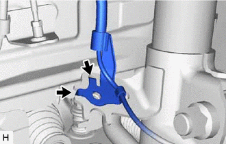
- Engage the 2 hooks to install the front speed sensor clamp bracket.

Hook NOTE:Do not twist the front speed sensor when installing it.
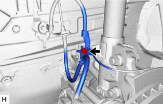
- Install the front flexible hose and front speed sensor to the front shock absorber assembly with the bolt.
Torque: 29 N.m (296 kgf/cm, 21 ft.lbf)
NOTE:Do not twist the front flexible hose when installing it.
- Engage the 2 hooks to install the front speed sensor clamp bracket.
- INSTALL FRONT WHEEL
Refer to PROCEDURE - Step 1
- CONNECT CABLE TO NEGATIVE AUXILIARY BATTERY TERMINAL (for HV Model)
- Connect the reservoir level switch connector.
- Install the brake master cylinder reservoir assembly to the reservoir bracket with the bolt and nut.
Torque: 9.0 N.m (92 kgf/cm, 80 in.lbf)
- Engage the clamp to install the wire harness to the brake master cylinder reservoir assembly.
- Connect the cable to the negative (-) auxiliary battery terminal.
Refer to PROCEDURE - Step 2
- Turn the ignition switch to ON (READY).
- Depress the brake pedal and release it.
- Clear the DTCs.
Refer to DTC CHECK / CLEAR [12/2019 - ]