Fuel Pump Control Circuit [12/2019 - 10/2022]: Procedure
- CHECK FUEL LEAK
- Check around and beneath the vehicle for fuel leaks, fumes, etc.
OK
No fuel leaks present.
Result
Proceed to OK NG
Result:
NG
REPAIR OR REPLACE FUEL LEAK POINT
Result:
OK
See step 2
- Check around and beneath the vehicle for fuel leaks, fumes, etc.
- PERFORM ACTIVE TEST USING GTS (ACTIVATE THE CIRCUIT RELAY)
- Check whether the fuel pump operating sound occurs when performing the Active Test on the GTS.
Powertrain > Engine > Active Test
Tester Display Activate the Circuit Relay Standard
GTS Operation Standard ON Operating sounds can be heard from fuel pump (for low pressure side) Result
Proceed to OK NG
Result:
NG
See step 8
Result:
OK
See step 3
- Check whether the fuel pump operating sound occurs when performing the Active Test on the GTS.
- PERFORM ACTIVE TEST USING GTS (CONTROL THE FUEL PUMP DUTY RATIO)
- Install the fuel pressure gauge (for low pressure line of low pressure side).
Refer to PROCEDURE - Step 2
- Compare the values in the Data List using the GTS and the fuel pressure gauge when the Active Test was performed.
Powertrain > Engine > Active Test
Active Test Display Control the Fuel Pump Duty Ratio Data List Display Fuel Pressure (Low) / Fuel Pressure 2 Standard
GTS Operation Standard Low Data List value and fuel pressure gauge are within +/-50 kPag of each other High HINT:
Perform "Inspection After Repair" after replacing the fuel pressure sensor (for low pressure side).
Refer to INITIALIZATION [12/2019 - 10/2022]
Result
Proceed to OK NG
Result:
NG
REPLACE FUEL DELIVERY PIPE WITH SENSOR ASSEMBLY. Refer to REMOVAL [12/2019 - 10/2022]
Result:
OK
See step 4
- Install the fuel pressure gauge (for low pressure line of low pressure side).
- READ VALUE USING GTS (FUEL PRESSURE)
- Read the values displayed on the GTS while the engine is cranking.
Powertrain > Engine > Data List
Tester Display Target Fuel Pressure (Low) / Target Fuel Pressure 2 Fuel Pressure (Low) / Fuel Pressure 2 Low Fuel Pressure Sensor Result
Result Proceed to Low Fuel Pressure Sensor value is within +/- 65 kPag of the Target Fuel Pressure (Low) / Target Fuel Pressure 2 A Low Fuel Pressure Sensor value is more than 65 kPag higher than the target fuel pressure (low) / Target Fuel Pressure 2 B Low Fuel Pressure Sensor value is more than 65 kPag lower than the target fuel pressure (low) / Target Fuel Pressure 2 C HINT:
Perform "Inspection After Repair" after replacing the fuel pump (for low pressure side).
Refer to INITIALIZATION [12/2019 - 10/2022]
Result:
B
REPLACE FUEL PUMP (FOR LOW PRESSURE SIDE)
Refer to REMOVAL [12/2019 - 10/2022]
HINT:
Relief blockage such as clogging of the jet pump is suspected.
Result:
C
See step 7
Result:
A
See step 5
- Read the values displayed on the GTS while the engine is cranking.
- CHECK FUEL PRESSURE
- Install the fuel pressure gauge (for low pressure line of low pressure side).
Refer to PROCEDURE - Step 2
- Start the engine.
- Measure the fuel pressure at idle.
Standard Fuel Pressure
196 to 833 kPa (2.0 to 8.5 kgf/cm2 , 28 to 121 psi)
HINT:
Refer to Standard Idle Speed.
Refer to PROCEDURE - Step 10
- Stop the engine.
- Check that the fuel pressure remains as specified for 5 minutes.
Standard Fuel Pressure
98 kPa (1.0 kgf/cm2 , 14.2 psi) or more
HINT:
Perform "Inspection After Repair" after replacing the fuel pump (for low pressure side).
Refer to INITIALIZATION [12/2019 - 10/2022]
Result
Proceed to OK NG
Result:
NG
REPLACE FUEL PUMP (FOR LOW PRESSURE SIDE). Refer to REMOVAL [12/2019 - 10/2022]
Result:
OK
See step 6
- Install the fuel pressure gauge (for low pressure line of low pressure side).
- CHECK SHORTAGE OF FUEL
- In accordance with the display on the GTS, check the value of Freeze Frame Data item "Fuel Remaining Volume" stored when the DTC was detected.
Powertrain > Engine > DTC (P0087-00) > Freeze Frame Data
Tester Display Fuel Remaining Volume Standard
Freeze Frame Data Item Specified Condition Fuel Remaining Volume 16% or more HINT:
- DTC P0087-00 may be stored if the vehicle temporarily ran out of fuel when the amount of fuel was low.
- If Freeze Frame Data item "Fuel Remaining Volume" is not displayed, based on the interview with the customer, check if the low fuel level warning was not displayed when the MIL illuminated.
Result
Proceed to OK NG
Result:
OK
PROCEED TO NEXT SUSPECTED AREA SHOWN IN PROBLEM SYMPTOMS TABLE. Refer to PROBLEM SYMPTOMS TABLE [12/2019 - 10/2022]
Result:
NG
END
- In accordance with the display on the GTS, check the value of Freeze Frame Data item "Fuel Remaining Volume" stored when the DTC was detected.
- CHECK SHORTAGE OF FUEL
- Check the amount of fuel remaining.
HINT:
- No fuel remains in the fuel tank: Malfunction of the fuel sender gauge assembly is suspected.
- Only the fuel pump side fuel chamber has no fuel remaining: Malfunction of the jet pump is suspected.
- Fuel remains in the fuel tank: Malfunction of the fuel pump (for low pressure side) is suspected.
- Perform "Inspection After Repair" after replacing the fuel pump (for low pressure side).
Refer to INITIALIZATION [12/2019 - 10/2022]
Result
Proceed to NEXT
Result:
NEXT
REPLACE FUEL PUMP (FOR LOW PRESSURE SIDE). Refer to REMOVAL [12/2019 - 10/2022]
- Check the amount of fuel remaining.
- PERFORM ACTIVE TEST USING GTS (FUEL PUMP SINGLE PHASE ENERGIZATION)
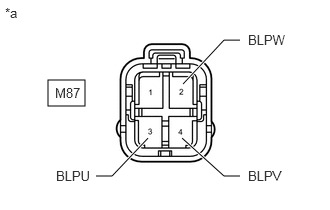
*a Front view of wire harness connector
(to Fuel Pump (for low pressure side))- Disconnect the fuel pump (for low pressure side) connector.
- Operate the fuel pump control ECU using the Active Test function and measure the voltage according to the value(s) in the table below.
Powertrain > Engine > Active Test
Tester Display Fuel Pump Single Phase Energization Standard Voltage
Tester Connection GTS Operation Specified Condition M87-3 (BLPU) - Body ground U Phase 4.4 to 8.4 V* M87-4 (BLPV) - Body ground V Phase 4.4 to 8.4 V* M87-2 (BLPW) - Body ground W Phase 4.4 to 8.4 V* HINT:
- *: This Active Test restricts the fuel pump control ECU output duty cycle to 50%. Therefore, the output voltage of the fuel pump control ECU will be approximately 50% of the power source voltage.
- Before performing this inspection, check that the battery voltage is between 11 and 14 V (not depleted).
- Perform "Inspection After Repair" after replacing the fuel pump (for low pressure side).
Refer to INITIALIZATION [12/2019 - 10/2022]
Result
Proceed to OK NG
Result:
OK
REPLACE FUEL PUMP (FOR LOW PRESSURE SIDE). Refer to REMOVAL [12/2019 - 10/2022]
Result:
NG
See step 9
- CHECK HARNESS AND CONNECTOR (FUEL PUMP CONTROL ECU - FUEL PUMP (FOR LOW PRESSURE SIDE))
- Disconnect the fuel pump control ECU connector.
- Disconnect the fuel pump (for low pressure side) connector.
- Measure the resistance according to the value(s) in the table below.
Standard Resistance
Tester Connection Condition Specified Condition M53-2 (FPU) - M87-3 (BLPU) Always Below 1 Ω M53-3 (FPV) - M87-4 (BLPV) Always Below 1 Ω M53-4 (FPW) - M87-2 (BLPW) Always Below 1 Ω M53-2 (FPU) or M87-3 (BLPU) - Body ground and other terminals Always 10 kΩ or higher M53-3 (FPV) or M87-4 (BLPV) - Body ground and other terminals Always 10 kΩ or higher M53-4 (FPW) or M87-2 (BLPW) - Body ground and other terminals Always 10 kΩ or higher Result
Proceed to OK NG
Result:
NG
REPAIR OR REPLACE HARNESS OR CONNECTOR
Result:
OK
See step 10
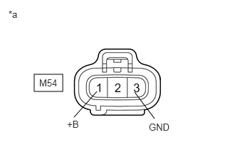
- CHECK HARNESS AND CONNECTOR (POWER SOURCE OF FUEL PUMP CONTROL ECU)
*a Front view of wire harness connector
(to Fuel Pump Control ECU)- Disconnect the fuel pump control ECU connector.
- Turn the ignition switch to ON.
- Measure the voltage according to the value(s) in the table below.
Standard Voltage
Tester Connection Condition Specified Condition M54-1 (+B) - M54-3 (GND) Ignition switch ON 11 to 14 V Result
Proceed to OK NG
Result:
NG
See step 13
Result:
OK
See step 11
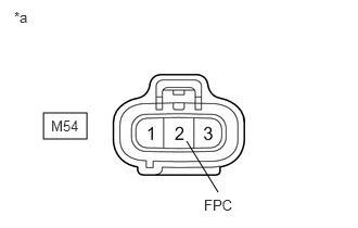
- INSPECT ECM (FPC TERMINAL)
*a Front view of wire harness connector
(to Fuel Pump Control ECU)- Disconnect the fuel pump control ECU connector.
- Operate the fuel pump control ECU using the Active Test function and measure the resistance according to the value(s) in the table below.
Powertrain > Engine > Active Test
Tester Display Fuel Pump Single Phase Energization Standard Resistance
Tester Connection GTS Operation Specified Condition M54-2 (FPC) - Body ground Before Active Test → During Active Test Before Active Test: Resistance is stable → During Active Test: Resistance fluctuates* HINT:
*: Using the Active Test, duty control of the transistors in the ECM will be performed. Due to the duty control, resistance of the FPC terminal will be unstable during the Active Test. If the resistance is stable before the Active Test and fluctuates while performing the Active Test, it can be determined that the transistor is operating. If the transistor does not operate during the Active Test, the ECM may be malfunctioning.
Result
Proceed to OK NG
Result:
OK
REPLACE FUEL PUMP CONTROL ECU. Refer to REMOVAL [12/2019 - 10/2022]
Result:
NG
See step 12
- CHECK HARNESS AND CONNECTOR (FUEL PUMP CONTROL ECU - ECM)
- Disconnect the fuel pump control ECU connector.
- Disconnect the ECM connector.
- Measure the resistance according to the value(s) in the table below.
Standard Resistance
Tester Connection Condition Specified Condition M54-2 (FPC) - A28-18 (FPC) Always Below 1 Ω M54-2 (FPC) or A28-18 (FPC) - Body ground and other terminals Always 10 kΩ or higher Result
Proceed to OK NG
Result:
OK
REPLACE ECM. Refer to REMOVAL [12/2019 - 09/2020] , or refer to REMOVAL [09/2020 - 10/2022]
Result:
NG
REPAIR OR REPLACE HARNESS OR CONNECTOR
- CHECK HARNESS AND CONNECTOR (FUEL PUMP CONTROL ECU - BODY GROUND)
- Disconnect the fuel pump control ECU connector.
- Measure the resistance according to the value(s) in the table below.
Standard Resistance
Tester Connection Condition Specified Condition M54-3 (GND) - Body ground Always Below 1 Ω Result
Proceed to OK NG
Result:
NG
REPAIR OR REPLACE HARNESS OR CONNECTOR
Result:
OK
See step 14
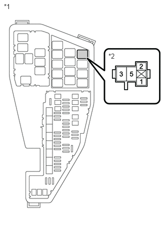
- CHECK HARNESS AND CONNECTOR (POWER SOURCE VOLTAGE OF FUEL PMP RELAY)
*1 No. 1 engine room relay block and No. 1 junction block assembly *2 FUEL PMP Relay - Remove the FUEL PMP relay from the No. 1 engine room relay block and No. 1 junction block assembly.
- Measure the voltage according to the value(s) in the table below.
Standard Voltage
Tester Connection Condition Specified Condition 5 (FUEL PMP relay) - Body ground Always 11 to 14 V Result
Proceed to OK NG
Result:
NG
REPAIR OR REPLACE HARNESS OR CONNECTOR (BATTERY - FUEL PMP RELAY)
Result:
OK
See step 15
- INSPECT FUEL PMP
Refer to PROCEDURE - Step 3
Result
Proceed to OK NG Result:
NG
REPLACE FUEL PMP RELAY
Result:
OK
See step 16
- CHECK HARNESS AND CONNECTOR (EFI-MAIN RELAY - FUEL PMP RELAY)
- Remove the EFI-MAIN relay, FUEL PMP relay and A/F HTR relay from the No. 1 engine room relay block and No. 1 junction block assembly.
HINT:
Remove the A/F HTR relay connected between the checked terminals as the coil inside the relay influences the measurement value.
- Measure the resistance according to the value(s) in the table below.
Standard Resistance
Tester Connection Condition Specified Condition 5 (EFI-MAIN relay) - 2 (FUEL PMP relay) Always Below 1 Ω 5 (EFI-MAIN relay) or 2 (FUEL PMP relay) - Body ground and other terminals Always 10 kΩ or higher Result
Proceed to OK NG
Result:
NG
REPAIR OR REPLACE HARNESS OR CONNECTOR
Result:
OK
See step 17
- Remove the EFI-MAIN relay, FUEL PMP relay and A/F HTR relay from the No. 1 engine room relay block and No. 1 junction block assembly.
- CHECK HARNESS AND CONNECTOR (FUEL PMP RELAY - BODY GROUND)
- Remove the FUEL PMP relay from the No. 1 engine room relay block and No. 1 junction block assembly.
- Measure the resistance according to the value(s) in the table below.
Standard Resistance
Tester Connection Condition Specified Condition 1 (FUEL PMP relay) - Body ground Always Below 1 Ω Result
Proceed to OK NG
Result:
NG
REPAIR OR REPLACE HARNESS OR CONNECTOR
Result:
OK
See step 18
- CHECK HARNESS AND CONNECTOR (FUEL PMP RELAY - FUEL PUMP CONTROL ECU)
- Remove the FUEL PMP relay from the No. 1 engine room relay block and No. 1 junction block assembly.
- Disconnect the fuel pump control ECU connector.
- Measure the resistance according to the value(s) in the table below.
Standard Resistance
Tester Connection Condition Specified Condition 5 (FUEL PMP relay) - M54-1 (+B) Always Below 1 Ω 5 (FUEL PMP relay) or M54-1 (+B) - Body ground and other terminals Always 10 kΩ or higher Result
Proceed to OK NG
Result:
OK
GO TO ECM POWER SOURCE CIRCUIT. Refer to ECM Power Source Circuit [12/2019 - 10/2022]
Result:
NG
REPAIR OR REPLACE HARNESS OR CONNECTOR