Removal [10/2022 - 11/2023]: Procedure
- DISABLE BRAKE CONTROL (for HV Model)
Refer to PROCEDURE - Step 4
- REMOVE REAR WHEEL
Refer to PROCEDURE - Step 1
- REMOVE REAR SUSPENSION ARM COVER
Refer to PROCEDURE - Step 3
- REMOVE REAR AXLE SHAFT NUT
Refer to PROCEDURE - Step 4
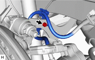
- SEPARATE REAR FLEXIBLE HOSE
- SEPARATE NO. 2 PARKING BRAKE WIRE ASSEMBLY
- Disconnect the No. 2 parking brake wire assembly connector from the parking brake actuator assembly.NOTE:
- Remove any dirt or foreign matter on and around the No. 2 parking brake wire assembly connector before performing this step.
- Do not allow water, oil or dirt to enter the No. 2 parking brake wire assembly connector.
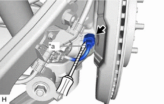
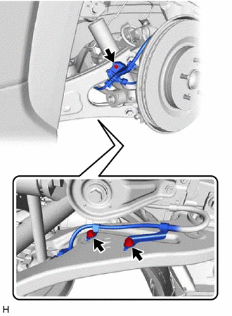
- Using a screwdriver with its tip wrapped with protective tape, disconnect the No. 2 parking brake wire assembly connector from the rear skid control sensor.
*a Protective Tape NOTE:- Remove any dirt or foreign matter on and around the No. 2 parking brake wire assembly connector before performing this step.
- Do not allow water, oil or dirt to enter the No. 2 parking brake wire assembly connector.
- Be careful not to damage the rear skid control sensor or connector cover.
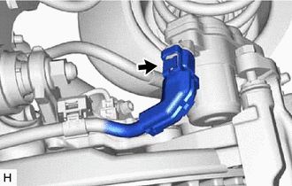
- Remove the bolt and separate the No. 2 parking brake wire assembly from the rear axle carrier sub-assembly.
- Remove the 3 bolts and separate the No. 2 parking brake wire assembly from the rear trailing arm assembly.
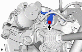
- Disconnect the No. 2 parking brake wire assembly connector from the parking brake actuator assembly.
- REMOVE REAR SKID CONTROL SENSOR
Refer to PROCEDURE - Step 6
- SEPARATE REAR DISC BRAKE CYLINDER ASSEMBLY
Refer to PROCEDURE - Step 4
- REMOVE REAR DISC BRAKE CYLINDER MOUNTING WITH BRAKE PAD
Refer to PROCEDURE - Step 5
- REMOVE REAR DISC
Refer to PROCEDURE - Step 16
- REMOVE REAR AXLE HUB AND BEARING ASSEMBLY
Refer to PROCEDURE - Step 10
- REMOVE REAR TRAILING ARM ASSEMBLY
Refer to PROCEDURE - Step 4
- REMOVE REAR AXLE CARRIER SUB-ASSEMBLY
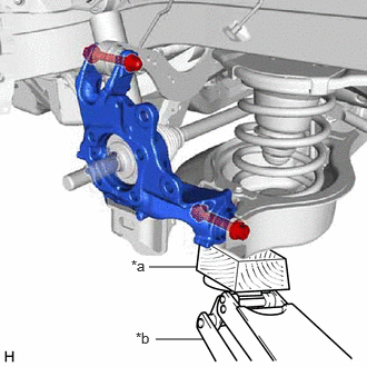
- Using a jack and a wooden block, support the rear No. 2 suspension arm assembly.NOTE:
- When jacking up the rear No. 2 suspension arm assembly, be sure to jack it up slowly.
- Keep supporting the rear No. 2 suspension arm assembly until the installation of the rear axle carrier sub-assembly has been completed.
- Make sure to perform this operation with the vehicle kept as low as possible.
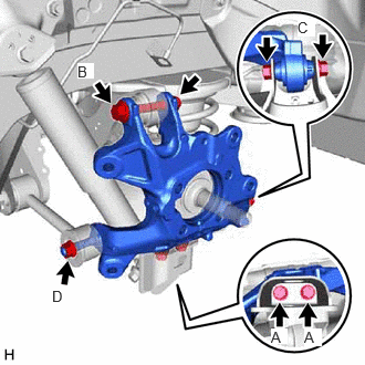
*a Wooden Block *b Jack - Remove the 2 bolts (A), and separate the rear lower shock absorber bracket sub-assembly from the rear axle carrier sub-assembly.
- Remove the bolt (B) and nut, and separate the rear upper control arm assembly from the rear axle carrier sub-assembly.NOTE:
Because the nut has its own stopper, do not turn the nut. Loosen the bolt with the nut secured.
- Remove the bolt (C) and nut, and separate the rear axle carrier sub-assembly from the rear No. 2 suspension arm assembly.NOTE:
Because the nut has its own stopper, do not turn the nut. Loosen the bolt with the nut secured.
- Remove the nut (D), spacer and rear axle carrier sub-assembly from the rear No. 1 suspension arm assembly.NOTE:
Use wire or an equivalent tool to keep the rear drive shaft assembly from hanging down.
- Using a jack and a wooden block, support the rear No. 2 suspension arm assembly.
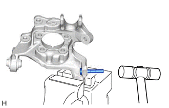
- REMOVE LOWER CONTROL ARM PIN