Installation [12/2019 - 10/2022]: Procedure
- INSTALL STUD BOLT
HINT:
If a stud bolt is deformed or its threads are damaged, replace it.
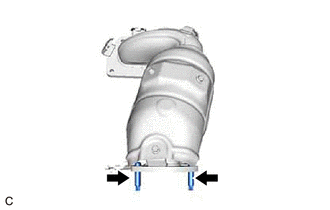
- Using an E8 "TORX" socket wrench, install the 2 stud bolts to the exhaust manifold assembly LH (TWC: Front Catalyst).
Torque: 19.5 N.m (199 kgf/cm, 14 ft.lbf)
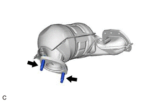
- Using an E8 "TORX" socket wrench, install the 2 stud bolts to the exhaust manifold assembly RH (TWC: Front Catalyst).
Torque: 19.5 N.m (199 kgf/cm, 14 ft.lbf)
- Using an E8 "TORX" socket wrench, install the 2 stud bolts to the exhaust manifold assembly LH (TWC: Front Catalyst).
- INSTALL EXHAUST MANIFOLD TO HEAD GASKET (for Bank 2)
- Install a new exhaust manifold to head gasket (for Bank 2) to the cylinder head sub-assembly.
- INSTALL EXHAUST MANIFOLD ASSEMBLY LH (TWC: Front Catalyst)
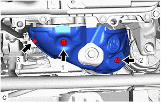
- Temporarily install the exhaust manifold assembly LH (TWC: Front Catalyst) with the 4 nuts.
- Tighten the 4 nuts in the order shown in the illustration.
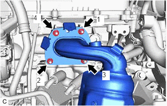 Courtesy of © TOYOTA, LICENSE AGREEMENT TMS1002
Torque: 21 N.m (214 kgf/cm, 15 ft.lbf)
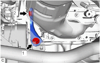
- INSTALL NO. 2 MANIFOLD STAY
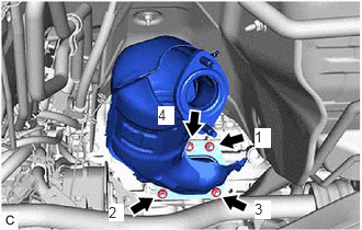
- Temporarily install the No. 2 manifold stay to the exhaust manifold assembly LH (TWC: Front Catalyst) and cylinder block sub-assembly with the bolt and nut.
- Tighten the bolt and nut in the order shown in the illustration.
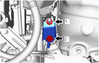 Courtesy of © TOYOTA, LICENSE AGREEMENT TMS1002
Torque: 34 N.m (347 kgf/cm, 25 ft.lbf)
- INSTALL NO. 2 EXHAUST MANIFOLD HEAT INSULATOR
- Install the No. 2 exhaust manifold heat insulator to the exhaust manifold assembly LH (TWC: Front Catalyst) with the 3 bolts in the order shown in the illustration.
Torque: 8.5 N.m (87 kgf/cm, 75 in.lbf)
- Install the No. 2 exhaust manifold heat insulator to the exhaust manifold assembly LH (TWC: Front Catalyst) with the 3 bolts in the order shown in the illustration.
- INSTALL NO. 1 SENSOR BRACKET
- Install the No. 1 sensor bracket to the cylinder head sub-assembly with the bolt.
Torque: 30 N.m (306 kgf/cm, 22 ft.lbf)
- Install the No. 1 sensor bracket to the cylinder head sub-assembly with the bolt.
- INSTALL AIR FUEL RATIO SENSOR (for Bank 2)
Refer to PROCEDURE - Step 3
- INSTALL V-BANK COVER SUB-ASSEMBLY
Refer to PROCEDURE - Step 52 [12/2019 - 09/2020] , or refer to PROCEDURE - Step 52 [09/2020 - 10/2022]
- INSTALL AIR FUEL RATIO SENSOR (for Bank 1)
Refer to PROCEDURE - Step 1
- INSTALL EXHAUST MANIFOLD TO HEAD GASKET (for Bank 1)
- Install a new exhaust manifold to head gasket (for Bank 1) to the cylinder head sub-assembly RH.
- INSTALL EXHAUST MANIFOLD ASSEMBLY RH (TWC: Front Catalyst)
- INSTALL MANIFOLD STAY
- Temporarily install the manifold stay to the exhaust manifold RH (TWC: Front Catalyst) and rear engine mounting bracket with the bolt and nut.
- Tighten the bolt and nut in the order shown in the illustration.
 Courtesy of © TOYOTA, LICENSE AGREEMENT TMS1002
Torque: 34 N.m (347 kgf/cm, 25 ft.lbf)
- INSTALL PROPELLER WITH CENTER BEARING SHAFT ASSEMBLY (for AWD)
Refer to INSTALLATION [12/2019 - 10/2022]
- INSTALL FRONT EXHAUST PIPE ASSEMBLY
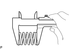
- Using a vernier caliper, measure the free length of the 2 compression springs.
Standard Length 40 mm (1.57 in.) Minimum Free Length 38.5 mm (1.52 in.) If the free length is less than minimum, replace the compression spring.
- Temporarily install a new gasket to the front exhaust pipe assembly.
- Using a plastic hammer and wooden block, tap in the gasket until its surface is flush with the front exhaust pipe assembly.
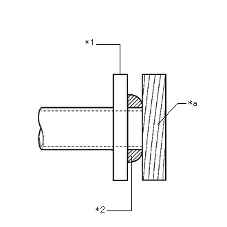
*1 Front Exhaust Pipe Assembly *2 Gasket *a Wooden Block NOTE:- Be careful with the installation direction of the gasket.
- Do not reuse the gasket.
- Do not damage the gasket.
- Do not push in the gasket by using the exhaust pipes when connecting them.
- Install 2 new gaskets to the front exhaust pipe assembly.
- Temporarily install the front exhaust pipe assembly with the 2 bolts, 4 new nuts and 2 compression springs.
- Tighten the 4 nuts.
Torque: 43 N.m (438 kgf/cm, 32 ft.lbf)
- Tighten the 2 bolts and 2 compression springs.
Torque: 43 N.m (438 kgf/cm, 32 ft.lbf)
HINT:
After installation, check that the space between the flanges of the center exhaust pipe assembly (TWC: Rear Catalyst) and front exhaust pipe assembly is consistent front-to-rear and left-to-right.
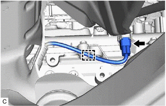
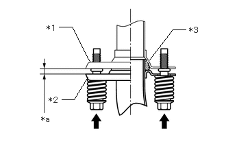
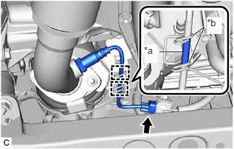
*1 Center Exhaust Pipe Assembly (TWC: Rear Catalyst) *2 Front Exhaust Pipe Assembly *3 Gasket *a Space between Flanges: 6.5 mm (0.256 in.) - Connect the heated oxygen sensor (for Bank 2) connector.
*a Tube *b Wire Harness Clamp - Engage the 2 wire harness clamps so that the tube is positioned as shown in the illustration.
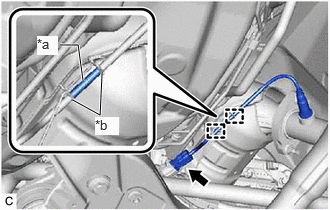
- Connect the heated oxygen sensor (for Bank 1) connector.
*a Tube *b Wire Harness Clamp - Engage the 2 wire harness clamps so that the tube is positioned as shown in the illustration.
- Using a vernier caliper, measure the free length of the 2 compression springs.
- INSTALL NO. 1 ENGINE UNDER COVER
Refer to PROCEDURE - Step 80 [12/2019 - 09/2020] , or refer to PROCEDURE - Step 80 [09/2020 - 10/2022]
- INSTALL FRONT WHEEL OPENING EXTENSION PAD LH
Refer to PROCEDURE - Step 81 [12/2019 - 09/2020] , or refer to PROCEDURE - Step 81 [09/2020 - 10/2022]
- INSTALL FRONT WHEEL OPENING EXTENSION PAD RH
Refer to PROCEDURE - Step 82 [12/2019 - 09/2020] , or refer to PROCEDURE - Step 82 [09/2020 - 10/2022]
- INSPECT FOR EXHAUST GAS LEAK
See step 6