Installation [12/2019 - 11/2023]: Procedure
- INSTALL BRAKE ACTUATOR BRACKET CUSHION
HINT:
Perform this procedure only when replacement of the brake actuator bracket cushions is necessary.
- Install the 3 brake actuator bracket cushions to the brake actuator bracket assembly.
- INSTALL NO. 2 BRAKE ACTUATOR CASE COLLAR
HINT:
Perform this procedure only when replacement of the No. 2 brake actuator case collars is necessary.
- Install the 3 No. 2 brake actuator case collars to the brake actuator bracket cushion.NOTE:
Make sure that the No. 2 brake actuator case collar is in full contact with the brake actuator bracket cushion.
- Install the 3 nuts.
Torque: 19 N.m (194 kgf/cm, 14 ft.lbf)
- Install the 3 No. 2 brake actuator case collars to the brake actuator bracket cushion.
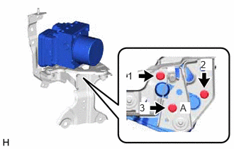
- INSTALL BRAKE ACTUATOR ASSEMBLY
- Temporarily install the brake actuator assembly to the brake actuator bracket assembly with the bolt (A).
- Install the brake actuator assembly to the brake actuator bracket assembly with the 3 bolts in the order shown in the illustration.
Torque: 6.5 N.m (66 kgf/cm, 58 in.lbf)
NOTE:- Do not remove the hole plugs of a new brake actuator assembly before connecting the brake tubes because the brake actuator assembly is filled with brake fluid.
- Do not hold the brake actuator assembly by the connector.
- Do not drop the brake actuator assembly when carrying it.
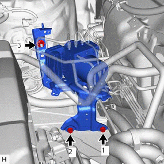
- INSTALL BRAKE ACTUATOR WITH BRACKET
- Temporarily install the brake actuator with bracket with the 2 bolts and nut.NOTE:
- Do not kink or damage the brake lines.
- Do not allow any foreign matter such as dirt or dust to enter the brake lines from the connecting parts.
- Be careful not to allow any brake fluid to enter the connector.
- Do not hold the brake actuator with bracket by the connector.
- Do not drop the brake actuator with bracket when carrying it.
HINT:
Install the brake actuator with bracket while avoiding the brake lines.
- Tighten the 2 bolts and nut in the order shown in the illustration.
Torque: 19 N.m (194 kgf/cm, 14 ft.lbf)
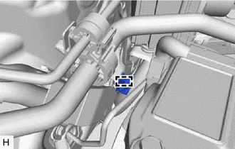
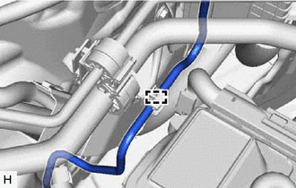
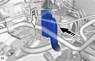
- Engage the clamp to install a new brake tube clamp.
- Return the front brake tube to its original position.NOTE:
Do not apply excessive force to the front brake tube.
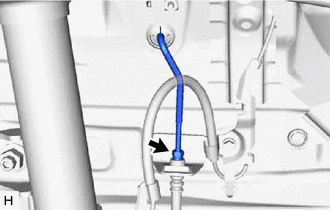
- Temporarily install the front brake tube to the front flexible hose.NOTE:
- Do not kink or damage the front brake tube.
- Do not allow any foreign matter such as dirt or dust to enter the front brake tube from the connecting parts.
- Engage the clamp to connect the front brake tube.NOTE:
Do not kink or damage the front brake tube.
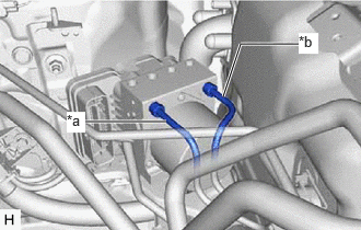
- Temporarily tighten the 2 brake lines to the correct position on the brake actuator assembly as shown in the illustration.
*a From 1st Chamber of Brake Master Cylinder Sub-assembly *b From 2nd Chamber of Brake Master Cylinder Sub-assembly NOTE:- Do not kink or damage the brake lines.
- Do not allow any foreign matter such as dirt or dust to enter the brake lines from the connecting parts.
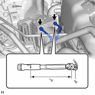
- Using a union nut wrench, fully tighten the 2 brake lines.
Specified tightening torque
Torque: 19.5 N.m (199 kgf/cm, 14 ft.lbf)
*a Torque Wrench Fulcrum Length *b Union Nut Wrench NOTE:Do not kink or damage the brake lines.
HINT:
- Calculate the torque wrench reading when changing the fulcrum length of the torque wrench.
Refer to PRECAUTION [12/2019 - 11/2023]
- When using a union nut wrench (fulcrum length of 20 mm (0.787 in.)) + torque wrench (fulcrum length of 162 mm (6.38 in.)):
17.4 N.m (177 kgf/cm, 13 ft.lbf)
- Calculate the torque wrench reading when changing the fulcrum length of the torque wrench.
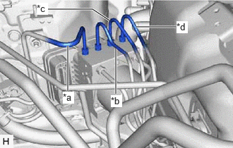
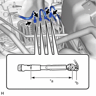
*a To Front Wheel Cylinder Assembly RH *b To Front Wheel Cylinder Assembly LH *c To Rear Wheel Cylinder Assembly RH *d To Rear Wheel Cylinder Assembly LH Temporarily tighten the 4 brake lines to the correct position on the brake actuator assembly as shown in the illustration.
NOTE:- Do not kink or damage the brake lines.
- Do not allow any foreign matter such as dirt or dust to enter the brake line from the connecting parts.
- Using a union nut wrench, fully tighten the 4 brake lines.
Specified tightening torque
Torque: 15.2 N.m (155 kgf/cm, 11 ft.lbf)
*a Torque Wrench Fulcrum Length *b Union Nut Wrench NOTE:Do not kink or damage the brake lines.
HINT:
- Calculate the torque wrench reading when changing the fulcrum length of the torque wrench.
Refer to PRECAUTION [12/2019 - 11/2023]
- When using a union nut wrench (fulcrum length of 22 mm (0.866 in.)) + torque wrench (fulcrum length of 162 mm (6.38 in.)):
13.4 N.m (137 kgf/cm, 10 ft.lbf)
- Calculate the torque wrench reading when changing the fulcrum length of the torque wrench.
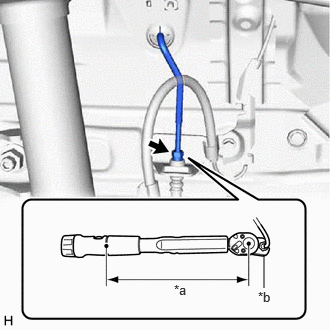
- Using a union nut wrench, fully tighten the front brake tube while holding the front flexible hose with a wrench.
Specified tightening torque
Torque: 15.2 N.m (155 kgf/cm, 11 ft.lbf)
*a Torque Wrench Fulcrum Length *b Union Nut Wrench NOTE:Do not kink or damage the front brake tube.
HINT:
- Calculate the torque wrench reading when changing the fulcrum length of the torque wrench.
Refer to PRECAUTION [12/2019 - 11/2023]
- When using a union nut wrench (fulcrum length of 22 mm (0.866 in.)) + torque wrench (fulcrum length of 162 mm (6.38 in.)):
13.4 N.m (137 kgf/cm, 10 ft.lbf)
- Calculate the torque wrench reading when changing the fulcrum length of the torque wrench.
- Install the brake lines with the bolt.
Torque: 7.0 N.m (71 kgf/cm, 62 in.lbf)
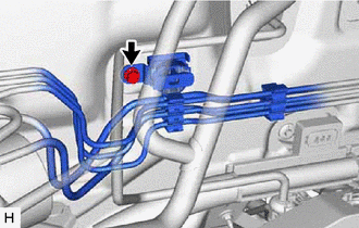
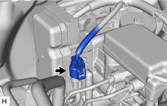
- Connect the connector to the brake actuator assembly and lock the lock lever.

Connect the connector 
Lock the lock lever NOTE:- Make sure that the connector is locked securely.
- Make sure that the actuator connector can be connected smoothly.
- Do not allow water, oil or dirt to enter the connector.
- Temporarily install the brake actuator with bracket with the 2 bolts and nut.
- CONNECT BRAKE BOOSTER WITH ACCUMULATOR PUMP CONNECTOR
HINT:
Perform this operation only when the accumulator pressure zero down could not be performed using the GTS.
- FILL RESERVOIR WITH BRAKE FLUID
- CONNECT CABLE TO NEGATIVE AUXILIARY BATTERY TERMINAL
Refer to INSTALLATION [12/2019 - 11/2023]
NOTE:When disconnecting the cable, some systems need to be initialized after the cable is reconnected.
Refer to INITIALIZATION [12/2019 - 09/2020] , or refer to INITIALIZATION [09/2020 - 10/2021] , or refer to INITIALIZATION [10/2021 - 10/2022] , or refer to INITIALIZATION [10/2022 - 11/2023]
- BLEED BRAKE SYSTEM
Refer to PROCEDURE - Step 3
- INSTALL COWL VENTILATOR PANEL SUB-ASSEMBLY
Refer to PROCEDURE - Step 15
- INSTALL FRONT UPPER SUSPENSION TO COWL BRACE SUB-ASSEMBLY LH
Refer to PROCEDURE - Step 16
- INSTALL FRONT UPPER SUSPENSION TO COWL BRACE SUB-ASSEMBLY RH
HINT:
Perform the same procedure as for the LH side.
- INSTALL FRONT FENDER SPLASH SHIELD SEAL FRONT LH
Refer to PROCEDURE - Step 18
- INSTALL FRONT FENDER SPLASH SHIELD SEAL FRONT RH
HINT:
Perform the same procedure as for the LH side.
- INSTALL FENDER SPLASH SHIELD SUB-ASSEMBLY REAR LH
Refer to PROCEDURE - Step 20
- INSTALL FENDER SPLASH SHIELD SUB-ASSEMBLY REAR RH
HINT:
Perform the same procedure as for the LH side.
- INSTALL WINDSHIELD WIPER MOTOR AND LINK ASSEMBLY
Refer to INSTALLATION [12/2019 - ]
- PERFORM INITIALIZATION AND CALIBRATION
for Electronically Controlled Brake System: Refer to UTILITY [12/2019 - 11/2023]
for Electric Parking Brake System: Refer to PRECAUTION [12/2019 - 10/2022] , or refer to PRECAUTION [10/2022 - 11/2023]
- CHECK AND CLEAR DTC
Refer to DTC CHECK / CLEAR [12/2019 - ]