Installation [12/2019 - ]: Procedure
- INSTALL TRANSMISSION CONTROL CABLE ASSEMBLY NOTE:
Before installing the transmission control cable assembly, check that the shift lever position sensor and shift lever are in N.
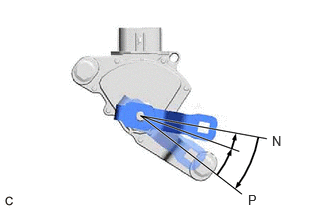
- Turn the control shaft lever clockwise until it stops, then turn it counterclockwise 2 notches.
- Engage the 2 claws to install a new clip to the transmission control cable assembly.
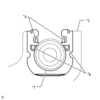
- Using a screwdriver, engage the 4 claws and install the transmission control cable assembly to the No. 1 transmission control cable bracket.
*1 Transmission Control Cable Assembly *2 No. 1 Transmission Control Cable Bracket *a Claw (A) *b Claw (B) NOTE:- Make sure that the claws (A) of the clip are securely engaged in the grooves of the bracket.
- Make sure that the transmission control cable assembly is securely installed inside of the claws (B) of the clip.
- Connect the transmission control cable assembly to the control shaft lever with the nut.
Torque: 12 N.m (122 kgf/cm, 9 ft.lbf)
NOTE:Before installing the transmission control cable assembly, check that the shift lever position sensor and shift lever are in N.
- Connect the transmission control cable assembly to the inverter with converter assembly with the 2 bolts.
Torque: 12 N.m (122 kgf/cm, 9 ft.lbf)
- Pass the transmission control cable assembly into the vehicle and install the transmission control cable assembly to the vehicle body with the 2 nuts.
Torque: 6.0 N.m (61 kgf/cm, 53 in.lbf)
- Connect the transmission control cable assembly to the vehicle body with the nut.
Torque: 6.0 N.m (61 kgf/cm, 53 in.lbf)
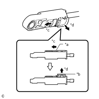
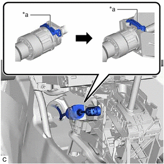
- Slide the slider of the transmission control cable assembly in the direction indicated by the arrow in the illustration and pull the lock piece outward.
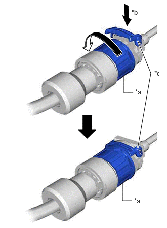
*a Slider *b Lock Piece *c Slide *d Pull - Turn the lock nut of the transmission control cable assembly counterclockwise. While holding the lock nut, push in the stopper.
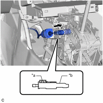
*a Lock Nut *b Push in *c Stopper NOTE:Do not turn the lock nut of the transmission control cable assembly excessively as the internal spring may come off and the transmission control cable assembly will not be reusable.
- Connect the transmission control cable assembly to the transmission floor shift assembly.
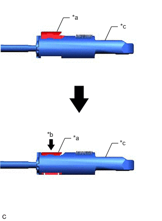
*a Stopper NOTE:- Install the transmission control cable assembly with the stopper facing upwards.
- After installation, check that the outer part of the stopper is as shown in the illustration.
- Make sure that the transmission control cable assembly is securely locked.
- Connect the transmission control cable assembly to the transmission floor shift assembly.
*a Lock Piece *b Adjuster Case NOTE:- Check that the lock piece is pulled out.
- Push the end of the transmission control cable assembly all the way to the base of the transmission floor shift assembly pin.
- Connect the transmission control cable assembly so that the lock piece faces the driver side.
- Push the lock piece into the adjuster case.
*a Lock Piece *b Push in *c Adjuster Case NOTE:- Check that the shift lever is in N.
- Securely push in the lock piece until the slider lock is engaged.
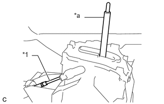
- When pushing in the lock piece of the adjuster case to lock it, remove your hand from the lever shaft.
*1 Transmission Control Cable Assembly *a Lever Shaft - When pushing in the lock piece of the adjuster case to lock it, do not move the lever shaft or transmission control cable assembly forward or backward.
- After adjusting the shift lever position, check the position and operation of the shift lever. If there is a problem, adjust the shift lever position again.
- Turn the control shaft lever clockwise until it stops, then turn it counterclockwise 2 notches.
- INSTALL FRONT CONSOLE BOX INSERT
Refer to PROCEDURE - Step 4 [12/2019 - 10/2022] , or refer to PROCEDURE - Step 4 [10/2022 - ]
- INSTALL NO. 1 INSTRUMENT PANEL UNDER COVER SUB-ASSEMBLY
Refer to PROCEDURE - Step 29 [12/2019 - 10/2022] , or refer to PROCEDURE - Step 28 [10/2022 - ]
- INSTALL NO. 1 SWITCH HOLE BASE
Refer to PROCEDURE - Step 26 [12/2019 - 10/2022] , or refer to PROCEDURE - Step 25 [10/2022 - ]
- INSTALL CONSOLE BOX ASSEMBLY
Refer to INSTALLATION [12/2019 - 10/2022] , or refer to INSTALLATION [10/2022 - ]
- CONNECT ENGINE ROOM MAIN WIRE
Refer to PROCEDURE - Step 16 [12/2019 - 11/2023] , or refer to PROCEDURE - Step 16 [11/2023 - ]
- CONNECT ENGINE WIRE
- Engage the clamp.
- Connect the engine wire with the 2 bolts.
Torque: 10 N.m (102 kgf/cm, 7 ft.lbf)
- Connect the ECM connector and rotate the lever to lock it.NOTE:
- When connecting the ECM connector, make sure that the connecting parts of the ECM connector is free of dirt, water and other foreign matter.
- Be sure to securely connect the ECM connector.
- Engage the clamp.
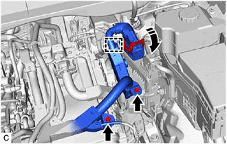
- INSTALL AIR CLEANER ASSEMBLY WITH AIR CLEANER HOSE
Refer to PROCEDURE - Step 19 [12/2019 - 11/2023] , or refer to PROCEDURE - Step 19 [11/2023 - ]
- INSTALL INLET AIR CLEANER ASSEMBLY
Refer to PROCEDURE - Step 20 [12/2019 - 11/2023] , or refer to PROCEDURE - Step 20 [11/2023 - ]
- INSTALL COOL AIR INTAKE DUCT SEAL
Refer to PROCEDURE - Step 4 [12/2019 - 09/2020] , or refer to PROCEDURE - Step 4 [09/2020 - ]
- INSTALL NO. 1 ENGINE COVER SUB-ASSEMBLY
Refer to PROCEDURE - Step 66 [12/2019 - 10/2022] , or refer to PROCEDURE - Step 66 [10/2022 - 11/2023] , or refer to PROCEDURE - Step 64 [11/2023 - ]
- INSPECT SHIFT LEVER POSITION
See step 2
- ADJUST SHIFT LEVER POSITION
See step 6