Removal [10/2022 - 11/2023]: Procedure
- PRECAUTION NOTE:
Make sure to select face mode before disconnecting the cable from the negative (-) auxiliary battery terminal.
- RECOVER REFRIGERANT FROM REFRIGERATION SYSTEM
See step 1
- REMOVE WINDSHIELD WIPER MOTOR AND LINK ASSEMBLY
Refer to REMOVAL [12/2019 - ]
- REMOVE FENDER SPLASH SHIELD SUB-ASSEMBLY REAR LH
Refer to PROCEDURE - Step 3
- REMOVE FENDER SPLASH SHIELD SUB-ASSEMBLY REAR RH
HINT:
Perform the same procedure as for the LH side.
- REMOVE FRONT FENDER SPLASH SHIELD SEAL FRONT LH
Refer to PROCEDURE - Step 5
- REMOVE FRONT FENDER SPLASH SHEILD SEAL FRONT RH
HINT:
Perform the same procedure as for the LH side.
- REMOVE FRONT UPPER SUSPENSION TO COWL BRACE SUB-ASSEMBLY LH
Refer to PROCEDURE - Step 7
- REMOVE FRONT UPPER SUSPENSION TO COWL BRACE SUB-ASSEMBLY RH
HINT:
Perform the same procedure as for the LH side.
- REMOVE COWL VENTILATOR PANEL SUB-ASSEMBLY
Refer to PROCEDURE - Step 9
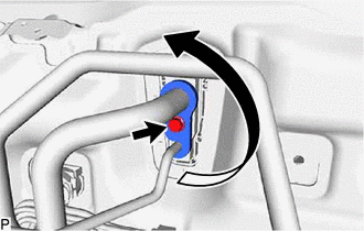
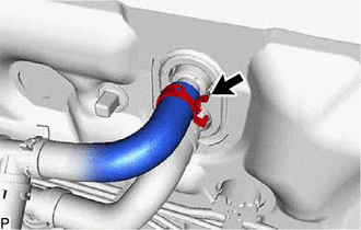
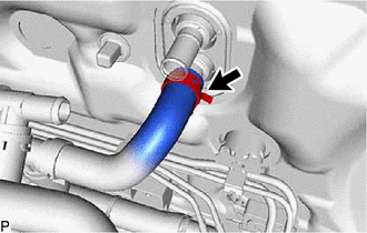
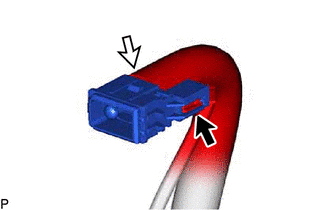
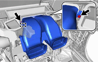
- DISCONNECT NO. 2 AIR CONDITIONER TUBE AND ACCESSORY ASSEMBLY
- Remove the bolt and rotate the hook connector as shown in the illustration.
- Disconnect the No. 2 air conditioner tube and accessory assembly.
- Remove the 2 O-rings from the No. 2 air conditioner tube and accessory assembly.NOTE:
Seal the openings of the disconnected parts using vinyl tape to prevent entry of moisture and foreign matter.
- Remove the bolt and rotate the hook connector as shown in the illustration.
- DISCONNECT OUTLET HEATER WATER HOSE B
- DISCONNECT INLET HEATER WATER HOSE B
- REMOVE FRONT SEAT ASSEMBLY RH (for Manual Seat)
Refer to REMOVAL [10/2022 - 11/2023]
- REMOVE FRONT SEAT ASSEMBLY (for Power Seat)
Refer to REMOVAL [10/2022 - 11/2023]
- REMOVE INSTRUMENT PANEL JUNCTION BLOCK ASSEMBLY WITH MAIN BODY ECU
Refer to REMOVAL [10/2022 - 11/2023]
- REMOVE METER MIRROR SUB-ASSEMBLY (w/ Headup Display)
Refer to REMOVAL [10/2022 - 11/2023]
- REMOVE NO. 4 AIR DUCT SUB-ASSEMBLY
Refer to PROCEDURE - Step 5
- REMOVE STEERING COLUMN ASSEMBLY
Refer to REMOVAL [10/2022 - 11/2023]
- REMOVE ECU INTEGRATION BOX RH
Refer to PROCEDURE - Step 7
- REMOVE PARKING ASSIST ECU WITH BRACKET
Refer to PROCEDURE - Step 3
- REMOVE NO. 1 CLEARANCE WARNING BUZZER
Refer to PROCEDURE - Step 24
- REMOVE COOLER (ROOM TEMP. SENSOR) THERMISTOR
- REMOVE ACCELERATOR PEDAL PAD
Refer to PROCEDURE - Step 5
- REMOVE ACCELERATOR PEDAL
Refer to PROCEDURE - Step 6
- REMOVE REAR NO. 2 AIR DUCT
- REMOVE REAR NO. 1 AIR DUCT
- REMOVE REAR NO. 4 AIR DUCT
- REMOVE REAR NO. 3 AIR DUCT
- REMOVE NO. 3 DASH PANEL INSULATOR PAD
- REMOVE CENTER HEATER TO REGISTER SUB DUCT
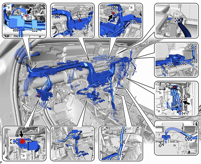
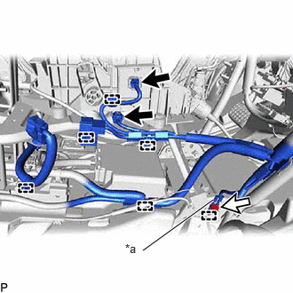
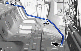
- DISCONNECT INSTRUMENT PANEL WIRE
- Disconnect the connector.
*a Earth Wire *b Connector Holder 
Bolt (A) 
Bolt (B) 
Connector 
Nut - Remove the 4 bolts (A) and disconnect the 4 earth wires.
- Remove the 2 nuts.
- Remove the bolt (B) and disconnect the connector holder.
- Disengage each clamp.
- Disconnect the 2 connectors.
*a Earth Wire Connector Bolt - Disengage each clamp.
- Remove the bolt and disconnect the earth wire.
- Disconnect the connector.
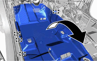
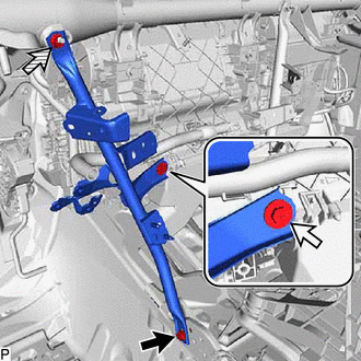
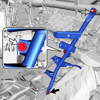
- REMOVE NO. 1 INSTRUMENT PANEL BRACE SUB-ASSEMBLY
- REMOVE NO. 2 INSTRUMENT PANEL BRACE SUB-ASSEMBLY
- REMOVE INSTRUMENT PANEL REINFORCEMENT ASSEMBLY WITH AIR CONDITIONER UNIT ASSEMBLY NOTE:
- Be sure to support the air conditioner unit assembly when removing it. Failure to do so may cause the bracket of the air conditioner unit assembly to break.
- When disassembling the air conditioner unit assembly, eliminate static electricity by touching the vehicle body to prevent the components from being damaged.
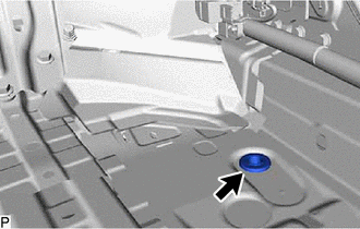
- Remove the clip.
- Disconnect the drain cooler hose.NOTE:
If the drain cooler hose is disconnected from the cooler unit drain hose grommet, make sure to replace the cooler unit drain hose grommet with a new one. Failure to do so may lead to water ingress.
- Remove the cooler unit drain hose grommet.
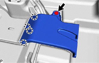
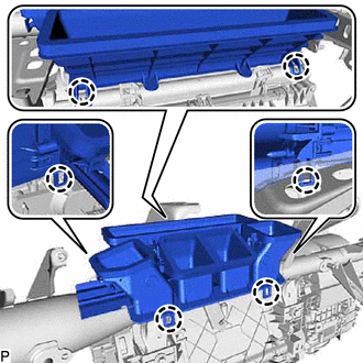
- Remove the 2 hole plugs.
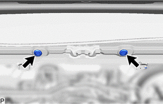
- Remove the 3 bolts.
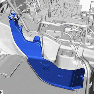
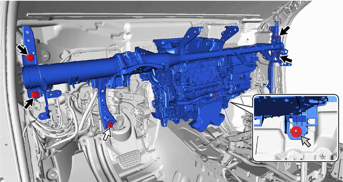
- Remove the 4 bolts (A).
Bolt (A) Bolt (B) Nut - - - Remove the bolt (B) and disconnect the brake pedal assembly.
- Remove the nut.
- Disengage each clamp.

Remove in this Direction - - - Disconnect the 4 connectors.
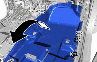
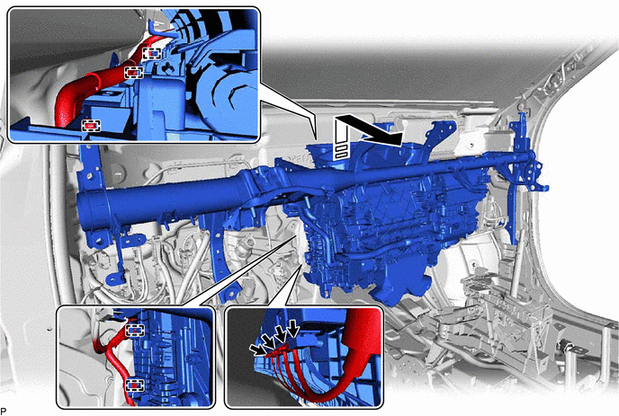
- Remove the instrument panel reinforcement assembly with air conditioner unit assembly as shown in the illustration.
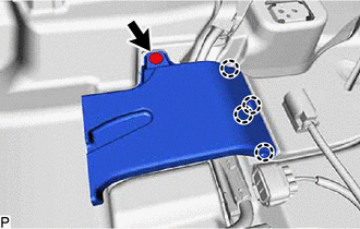
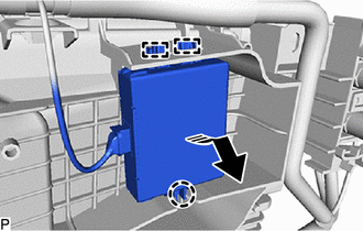
- Disengage the claw and 2 guides to disconnect the ID code box (immobiliser code ECU) as shown in the illustration.
Remove in this Direction
- REMOVE CENTER HEATER TO REGISTER DUCT
- REMOVE AIR CONDITIONER UNIT ASSEMBLY