Installation [12/2019 - 10/2022]: Procedure
- INSTALL HEATER WATER PUMP ASSEMBLY
- Temporarily install the heater water pump assembly with the bolt and 3 nuts.
Torque: 9.8 N.m (100 kgf/cm, 87 in.lbf)
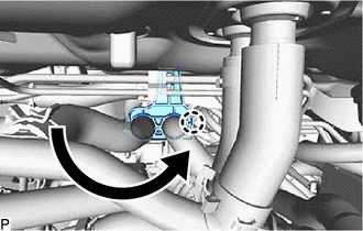
- Engage the clamp.
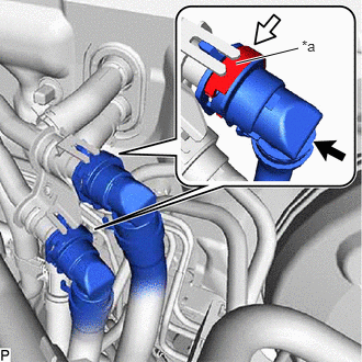
- Connect the connector.
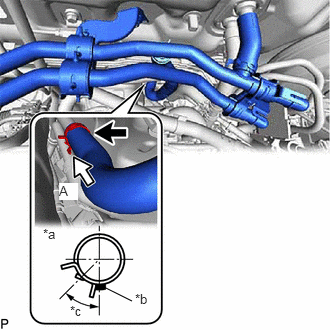
- Connect the water hose with the marking facing down and engage the clip within the area shown in the illustration.NOTE:
Do not apply excessive force to the water hose.
*a View A *b Marking (White) *c Clip Installation Angle (0 to 60°) - Engage the claw to the original position as shown in the illustration.
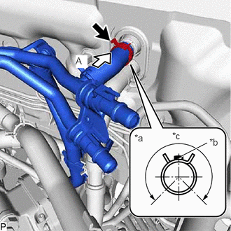
- Connect the water hose with the marking facing up and engage the clip within the area shown in the illustration.NOTE:
Do not apply excessive force to the water hose.
*a View A *b Marking (Green) *c Clip Installation Angle (270°)
- Temporarily install the heater water pump assembly with the bolt and 3 nuts.
- CONNECT WATER BY-PASS HOSE ASSEMBLY
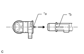
- Align the protrusion of the water by-pass hose assembly connector with the cutout in the heater water pump assembly and securely insert the water by-pass hose assembly connector to the stopper of the pipe.
*a Protrusion *b Cutout - Push in the retainer.
*a Retainer 
Push 
Push in - Check that the heater water pump assembly and water by-pass hose assembly connector are securely connected by pulling on them.
- Align the protrusion of the water by-pass hose assembly connector with the cutout in the heater water pump assembly and securely insert the water by-pass hose assembly connector to the stopper of the pipe.
- INSTALL COWL VENTILATOR PANEL SUB-ASSEMBLY
Refer to PROCEDURE - Step 15
- INSTALL FRONT UPPER SUSPENSION TO COWL BRACE SUB-ASSEMBLY LH
Refer to PROCEDURE - Step 16
- INSTALL FRONT UPPER SUSPENSION TO COWL BRACE SUB-ASSEMBLY RH
HINT:
Perform the same procedure as for the LH side.
- INSTALL FRONT FENDER SPLASH SHIELD SEAL FRONT LH
Refer to PROCEDURE - Step 18
- INSTALL FRONT FENDER SPLASH SHEILD SEAL FRONT RH
HINT:
Perform the same procedure as for the LH side.
- INSTALL FENDER SPLASH SHIELD SUB-ASSEMBLY REAR LH
Refer to PROCEDURE - Step 20
- INSTALL FENDER SPLASH SHIELD SUB-ASSEMBLY REAR RH
HINT:
Perform the same procedure as for the LH side.
- INSTALL WINDSHIELD WIPER MOTOR AND LINK ASSEMBLY
Refer to INSTALLATION [12/2019 - ]
- ADD ENGINE COOLANT
Refer to PROCEDURE - Step 2
- INSPECT FOR COOLANT LEAK
Refer to PROCEDURE - Step 1
- INSTALL REAR ENGINE UNDER COVER RH
Refer to PROCEDURE - Step 78 [12/2019 - 09/2020] , or refer to PROCEDURE - Step 78 [09/2020 - 10/2022]
- INSTALL REAR ENGINE UNDER COVER LH
Refer to PROCEDURE - Step 79 [12/2019 - 09/2020] , or refer to PROCEDURE - Step 79 [09/2020 - 10/2022]
- INSTALL NO. 1 ENGINE UNDER COVER
Refer to PROCEDURE - Step 80 [12/2019 - 09/2020] , or refer to PROCEDURE - Step 80 [09/2020 - 10/2022]
- INSTALL FRONT WHEEL OPENING EXTENSION PAD LH
Refer to PROCEDURE - Step 81 [12/2019 - 09/2020] , or refer to PROCEDURE - Step 81 [09/2020 - 10/2022]
- INSTALL FRONT WHEEL OPENING EXTENSION PAD RH
Refer to PROCEDURE - Step 82 [12/2019 - 09/2020] , or refer to PROCEDURE - Step 82 [09/2020 - 10/2022]