Installation [10/2022 - 11/2023]: Procedure
- INSTALL SIDE AIRBAG SENSOR ASSEMBLY
- Check that the ignition switch is off.
- Check that the cable is disconnected from the negative (-) auxiliary battery terminal.WARNING:
Wait at least 90 seconds after disconnecting the cable from the negative (-) auxiliary battery terminal to disable the SRS system.
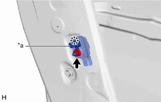
- Insert the side airbag sensor assembly stopper into the door hole, engage the claw and install the side airbag sensor assembly to the front door panel with the nut.
Torque: 9.0 N*m (92 kgf*cm, 80 in.*lbf)
NOTE:- If the side airbag sensor assembly has been dropped, or there are any cracks, dents or other defects in the case or connector, replace it with a new one.
- When installing the side airbag sensor assembly, make sure that the SRS wiring does not interfere with or is not pinched between other parts.
- Make sure that the side airbag sensor assembly stopper is securely inserted into the door hole.
- Keep the stud bolt and waterproof rubber seal free of foreign matter.
*a Stopper - Connect the connector to the side airbag sensor assembly.NOTE:
When connecting any airbag connector, take care not to damage the airbag wire harness.
HINT:
Refer to How to Connect or Disconnect Airbag Connector.
Refer to HOW TO CONNECT OR DISCONNECT AIRBAG CONNECTOR [12/2019 - 11/2023]
- Check that there is no looseness in the installed parts of the side airbag sensor assembly.
- INSTALL FRONT DOOR SERVICE HOLE COVER
Refer to PROCEDURE - Step 26
- INSTALL FRONT DOOR WEATHERSTRIP CLIP
Refer to PROCEDURE - Step 27
- INSTALL FRONT DOOR TRIM BOARD SUB-ASSEMBLY
Refer to PROCEDURE - Step 39
- INSTALL COURTESY LIGHT ASSEMBLY
Refer to PROCEDURE - Step 2
- INSTALL MULTIPLEX NETWORK MASTER SWITCH ASSEMBLY WITH FRONT DOOR UPPER ARMREST BASE PANEL (for Driver Side)
Refer to PROCEDURE - Step 42
- INSTALL POWER WINDOW REGULATOR SWITCH ASSEMBLY WITH FRONT DOOR UPPER ARMREST BASE PANEL (for Front Passenger Side)
Refer to PROCEDURE - Step 43
- INSTALL FRONT DOOR INSIDE HANDLE BEZEL
Refer to PROCEDURE - Step 41
- INSTALL FRONT DOOR LOWER FRAME BRACKET GARNISH
Refer to PROCEDURE - Step 44
- CONNECT CABLE TO NEGATIVE AUXILIARY BATTERY TERMINAL
for T24A-FTS: Refer to PROCEDURE - Step 4
for A25A-FXS: Refer to PROCEDURE - Step 2
NOTE:When disconnecting the cable, some systems need to be initialized after the cable is reconnected.
Refer to INITIALIZATION [10/2022 - 11/2023]
- INSTALL BATTERY SERVICE HOLE COVER (for HV Model)
Refer to PROCEDURE - Step 3
- INSPECT POWER WINDOW OPERATION
Refer to OPERATION CHECK [12/2019 - ]
- PERFORM DIAGNOSTIC SYSTEM CHECK
- INSPECT SRS WARNING LIGHT
Refer to OPERATION CHECK [10/2022 - 11/2023]