Installation [12/2019 - ]: Procedure
- INSTALL REAR AXLE HUB AND BEARING ASSEMBLY
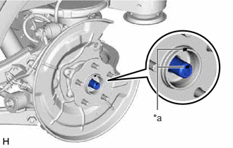
- Install the rear axle hub and bearing assembly and rear disc brake dust cover sub-assembly to the rear drive shaft assembly.NOTE:
Align the matchmarks on the rear drive shaft assembly and rear axle hub and bearing assembly.
*a Matchmark - Install the rear axle hub and bearing assembly to the rear axle carrier sub-assembly with the 4 bolts.
Torque: 121 N.m (1234 kgf/cm, 89 ft.lbf)
- Install the rear axle hub and bearing assembly and rear disc brake dust cover sub-assembly to the rear drive shaft assembly.
- INSTALL REAR DISC
Refer to PROCEDURE - Step 1
- INSTALL REAR DISC BRAKE CYLINDER MOUNTING WITH BRAKE PAD
See step 10 [12/2019 - 10/2022], or see step 10 [10/2022 - 11/2023], or see step 10 [11/2023 - ]
- INSTALL REAR DISC BRAKE CYLINDER ASSEMBLY
- Hold the 2 rear disc brake cylinder slide pins, and install the rear disc brake cylinder assembly to the rear disc brake cylinder mounting with 2 bolts.
Torque: 34.3 N.m (350 kgf/cm, 25 ft.lbf)
HINT:
The bolts can be reused while inspecting the rear axle hub and bearing assembly for looseness and runout. However, make sure to replace the bolts with new ones after the inspection is complete.
- Hold the 2 rear disc brake cylinder slide pins, and install the rear disc brake cylinder assembly to the rear disc brake cylinder mounting with 2 bolts.
- TEMPORARILY INSTALL REAR AXLE SHAFT NUT
- Clean the threaded parts on the rear drive shaft assembly and a new rear axle shaft nut using non-residue solvent.NOTE:
- Be sure to perform this work even when using a new rear drive shaft assembly.
- Keep the threaded parts free of oil and foreign matter.
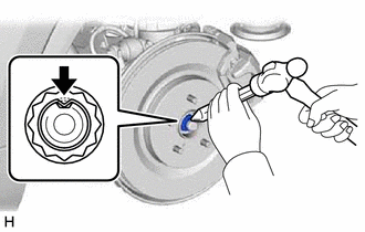
- Using a 30 mm deep socket wrench, temporarily install the rear axle shaft nut.
Torque: 294 N.m (2998 kgf/cm, 217 ft.lbf)
NOTE:Stake the rear axle shaft nut after inspecting for looseness and runout in the following steps.
HINT:
Keep depressing the brake pedal to prevent the rear drive shaft assembly from rotating.
- Clean the threaded parts on the rear drive shaft assembly and a new rear axle shaft nut using non-residue solvent.
- SEPARATE REAR DISC BRAKE CYLINDER ASSEMBLY
See step 4 [12/2019 - 10/2022], or see step 4 [10/2022 - 11/2023], or see step 4 [11/2023 - ]
- REMOVE REAR DISC BRAKE CYLINDER MOUNTING WITH BRAKE PAD
See step 5 [12/2019 - 10/2022], or see step 5 [10/2022 - 11/2023], or see step 5 [11/2023 - ]
- REMOVE REAR DISC
Refer to PROCEDURE - Step 16 [12/2019 - 10/2022] , or refer to PROCEDURE - Step 16 [10/2022 - 11/2023] , or refer to PROCEDURE - Step 16 [11/2023 - ]
- INSPECT REAR AXLE HUB BEARING LOOSENESS
See step 7 [12/2019 - 10/2022], or see step 7 [10/2022 - 11/2023], or see step 7 [11/2023 - ]
- INSPECT REAR AXLE HUB RUNOUT
See step 8 [12/2019 - 10/2022], or see step 8 [10/2022 - 11/2023], or see step 8 [11/2023 - ]
- INSTALL REAR DISC
Refer to PROCEDURE - Step 1
- INSTALL REAR DISC BRAKE CYLINDER MOUNTING WITH BRAKE PAD
See step 10 [12/2019 - 10/2022], or see step 10 [10/2022 - 11/2023], or see step 10 [11/2023 - ]
- INSTALL REAR DISC BRAKE CYLINDER ASSEMBLY
See step 11 [12/2019 - 10/2022], or see step 11 [10/2022 - 11/2023], or see step 11 [11/2023 - ]
- INSTALL REAR SKID CONTROL SENSOR
- Install the rear skid control sensor to the rear axle carrier sub-assembly with the bolt.
Torque: 8.5 N.m (87 kgf/cm, 75 in.lbf)
NOTE:- Keep the tip of the rear skid control sensor and installation hole free of foreign matter.
- Firmly insert the rear skid control sensor body into the rear axle carrier sub-assembly before tightening the bolt.
- After installing the rear skid control sensor to the rear axle carrier sub-assembly, make sure that there is no clearance between the rear skid control sensor stay and rear axle carrier sub-assembly. Also make sure that no foreign matter is stuck between the parts.
- Install the rear skid control sensor to the rear axle carrier sub-assembly with the bolt.
- CONNECT NO. 2 PARKING BRAKE WIRE ASSEMBLY
- Connect the No. 2 parking brake wire assembly connector to the rear skid control sensor.
- Connect the No. 2 parking brake wire assembly connector to the parking brake actuator assembly.
- STAKE REAR AXLE SHAFT NUT
- INSTALL REAR SUSPENSION ARM COVER
Refer to PROCEDURE - Step 9 [12/2019 - 10/2022] , or refer to PROCEDURE - Step 9 [10/2022 - ]
- INSTALL REAR WHEEL
Refer to PROCEDURE - Step 1 [12/2019 - 10/2022] , or refer to PROCEDURE - Step 1 [10/2022 - ]
- CONNECT CABLE TO NEGATIVE AUXILIARY BATTERY TERMINAL (for HV Model)
- Connect the reservoir level switch connector.
- Install the brake master cylinder reservoir assembly to the reservoir bracket with the bolt and nut.
Torque: 9.0 N.m (92 kgf/cm, 80 in.lbf)
- Engage the clamp to install the wire harness to the brake master cylinder reservoir assembly.
- Connect the cable to the negative (-) auxiliary battery terminal.
Refer to PROCEDURE - Step 2 [12/2019 - 11/2023] , or refer to PROCEDURE - Step 2 [11/2023 - ]
- Turn the ignition switch to ON (READY).
- Depress the brake pedal and release it.
- Clear the DTCs.
Refer to DTC CHECK / CLEAR [12/2019 - ]
- CHECK FOR SPEED SENSOR SIGNAL
for HV Model: Refer to TEST MODE PROCEDURE [12/2019 - 11/2023] , or refer to TEST MODE PROCEDURE [11/2023 - ]
for Gasoline Model: Refer to TEST MODE PROCEDURE [12/2019 - 11/2023] , or refer to TEST MODE PROCEDURE [11/2023 - ]