Installation [10/2022 - ]: Procedure
- PRECAUTION NOTE:
After turning the ignition switch off, waiting time may be required before disconnecting the cable from the negative (-) auxiliary battery terminal. Therefore, make sure to read the disconnecting the cable from the negative (-) auxiliary battery terminal notices before proceeding with work.
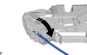
- INSTALL FRONT DOOR INSIDE LOCKING CABLE ASSEMBLY
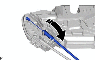
- INSTALL FRONT DOOR LOCK REMOTE CONTROL CABLE ASSEMBLY
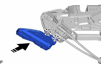
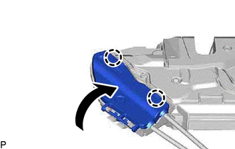
- INSTALL FRONT DOOR LOCK COVER SUB-ASSEMBLY
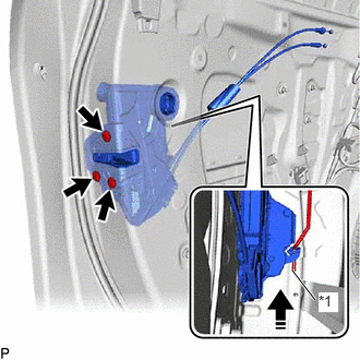
- INSTALL FRONT DOOR LOCK WITH MOTOR ASSEMBLY NOTE:
- When reusing a removed front door lock with motor assembly, replace the door lock wiring harness seal with a new one.
- Do not allow grease or dust to adhere to the door lock wiring harness seal installation surface.
- Reusing a door lock wiring harness seal or using a damaged door lock wiring harness seal may cause water ingress. This may result in a malfunction of the front door lock with motor assembly.
- Apply MP grease to the sliding parts of the front door lock with motor assembly.
- When reusing the front door lock with motor assembly:
- Install a new door lock wiring harness seal to the front door lock with motor assembly.
- Connect the front door lock open rod to the front door lock with motor assembly as shown in the illustration.
*1 Front Door Lock Open Rod 
Install in this Direction HINT:
Make sure that the front door lock open rod is securely connected to the front door lock with motor assembly.
- Using a T30 "TORX" socket wrench, install the front door lock with motor assembly with the 3 screws.
Torque: 5.0 N.m (51 kgf/cm, 44 in.lbf)
- INSTALL FRONT DOOR SERVICE HOLE COVER
Refer to PROCEDURE - Step 26
- INSTALL FRONT DOOR WEATHERSTRIP CLIP
Refer to PROCEDURE - Step 27
- INSTALL FRONT DOOR TRIM BOARD SUB-ASSEMBLY
Refer to PROCEDURE - Step 39
- INSTALL COURTESY LIGHT ASSEMBLY
Refer to PROCEDURE - Step 2
- INSTALL FRONT DOOR INSIDE HANDLE BEZEL
Refer to PROCEDURE - Step 41
- INSTALL MULTIPLEX NETWORK MASTER SWITCH ASSEMBLY WITH FRONT DOOR UPPER ARMREST BASE PANEL (for Driver Side)
Refer to PROCEDURE - Step 42
- INSTALL POWER WINDOW REGULATOR SWITCH ASSEMBLY WITH FRONT DOOR UPPER ARMREST BASE PANEL (for Front Passenger Side)
Refer to PROCEDURE - Step 43
- INSTALL FRONT DOOR LOWER FRAME BRACKET GARNISH
Refer to PROCEDURE - Step 44
- CONNECT CABLE TO NEGATIVE AUXILIARY BATTERY TERMINAL
for T24A-FTS:
Refer to PROCEDURE - Step 4 [10/2022 - 11/2023] , or refer to PROCEDURE - Step 4 [11/2023 - ]
for A25A-FXS:
Refer to PROCEDURE - Step 2 [12/2019 - 11/2023] , or refer to PROCEDURE - Step 2 [11/2023 - ]
- INSTALL BATTERY SERVICE HOLE COVER (for HV Model)
Refer to PROCEDURE - Step 3 [12/2019 - 11/2023] , or refer to PROCEDURE - Step 3 [11/2023 - ]
- INITIALIZE POWER WINDOW CONTROL SYSTEM
Refer to INITIALIZATION [12/2019 - ]
- INSPECT POWER WINDOW OPERATION
Refer to OPERATION CHECK [12/2019 - ]