Adjustment [12/2019 - 10/2022]: Procedure
- INSPECT AND ADJUST BRAKE PEDAL HEIGHT
- Remove the front door scuff plate LH.
Refer to PROCEDURE - Step 9
- Remove the cowl side trim sub-assembly LH.
Refer to PROCEDURE - Step 10
- Remove the accelerator pedal pad.
Refer to PROCEDURE - Step 5
- Remove the accelerator pedal.
Refer to PROCEDURE - Step 6
- Check the brake pedal height.
HINT:
Inspect and adjust the brake pedal height with the floor carpet and front floor mat folded back.
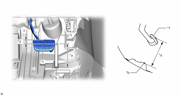
- Measure the shortest distance between the brake pedal pad surface and floor panel as shown in the illustration.
*1 Brake Pedal Pad - - *a Brake Pedal Height *b Measuring Plane of Floor Panel *c Ruler *d 36 mm (1.42 in.) Brake Pedal Height from Floor Panel
155.6 to 171.6 mm (6.13 to 6.76 in.)
HINT:
If the brake pedal height is not as specified, inspect and adjust the push rod length according to the procedure below.
- Measure the shortest distance between the brake pedal pad surface and floor panel as shown in the illustration.
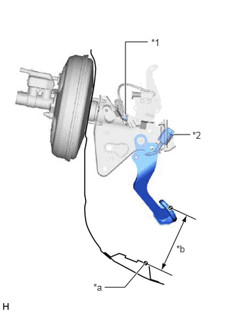
- Adjust the push rod length.
- Remove the stop light switch assembly.
*1 Lock Nut *2 Stop Light Switch Assembly *a Floor Panel *b Brake Pedal Height Refer to REMOVAL [12/2019 - ]
- Loosen the lock nut.
- Adjust the brake pedal height by turning the push rod.
Brake Pedal Height from Floor Panel
155.6 to 171.6 mm (6.13 to 6.76 in.)
- Tighten the lock nut.
Torque: 26 N.m (265 kgf/cm, 19 ft.lbf)
- Install the stop light switch assembly.
Refer to INSTALLATION [12/2019 - ]
- Remove the stop light switch assembly.
- Install the accelerator pedal.
Refer to PROCEDURE - Step 1
- Install the accelerator pedal pad.
Refer to PROCEDURE - Step 2
- Install the cowl side trim sub-assembly LH.
Refer to PROCEDURE - Step 51
- Install the front door scuff plate LH.
Refer to PROCEDURE - Step 52
- Remove the front door scuff plate LH.
- INSPECT BRAKE PEDAL FREE PLAY
- Stop the engine and firmly depress the brake pedal several times until no vacuum is left in the brake booster.
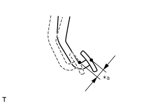
- Depress the brake pedal until a slight resistance is felt. Measure the distance as shown in the illustration.
*a Brake Pedal Free Play Brake Pedal Free Play
1.0 to 6.0 mm (0.0394 to 0.236 in.)
HINT:
- If the brake pedal free play is not as specified, check the stop light switch clearance.
Refer to INSTALLATION [12/2019 - ]
- If the brake pedal free play is as specified, proceed to the Inspect Brake Pedal Reserve Distance procedure.
- If the brake pedal free play is not as specified, check the stop light switch clearance.
- INSPECT BRAKE PEDAL RESERVE DISTANCE
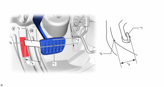
- With the engine running, depress the brake pedal and measure the brake pedal reserve distance as shown in the illustration.
*1 Brake Pedal Pad - - *a Brake Pedal Reserve Distance *b Measuring Plane of Floor Panel *c Ruler *d 36 mm (1.42 in.) Brake Pedal Reserve Distance from Floor Panel at 300 N (31 kgf, 67.4 lbf)
94 mm (3.70 in.) or more
HINT:
If the distance is not as specified, troubleshoot the brake system.
Refer to PROBLEM SYMPTOMS TABLE [12/2019 - ]
- With the engine running, depress the brake pedal and measure the brake pedal reserve distance as shown in the illustration.