Installation [11/2023 - ]: Procedure
- INSTALL NO. 2 BRAKE POWER SUPPLY BRACKET
- Using a 5 mm long hexagon socket wrench, install the No. 2 brake power supply bracket with the 2 bolts.
Torque: 6.5 N.m (66 kgf/cm, 58 in.lbf)
- Using a 5 mm long hexagon socket wrench, install the No. 2 brake power supply bracket with the 2 bolts.
- INSTALL NO. 3 BRAKE POWER SUPPLY BRACKET
- Using a 5 mm long hexagon socket wrench, install the No. 3 brake power supply bracket with the 2 bolts.
Torque: 6.5 N.m (66 kgf/cm, 58 in.lbf)
- Using a 5 mm long hexagon socket wrench, install the No. 3 brake power supply bracket with the 2 bolts.
- INSTALL NO. 2 WIRE CLAMP BRACKET
- Using a 5 mm long hexagon socket wrench, install the No. 2 wire clamp bracket with the bolt.
Torque: 6.5 N.m (66 kgf/cm, 58 in.lbf)
- Using a 5 mm long hexagon socket wrench, install the No. 2 wire clamp bracket with the bolt.
- INSTALL NO. 1 WIRE CLAMP BRACKET
- Using a 5 mm long hexagon socket wrench, install the No. 1 wire clamp bracket with the bolt.
Torque: 6.5 N.m (66 kgf/cm, 58 in.lbf)
- Using a 5 mm long hexagon socket wrench, install the No. 1 wire clamp bracket with the bolt.
- INSTALL BRAKE BOOSTER WITH ACCUMULATOR PUMP ASSEMBLY
See step 1
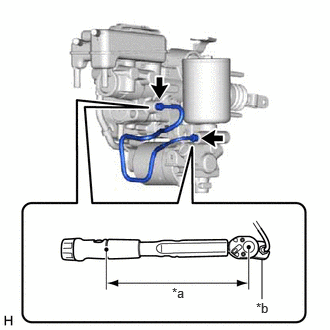
- INSTALL NO. 1 BRAKE ACTUATOR TUBE
- Using a union nut wrench, install the No. 1 brake actuator tube.
*a Torque Wrench Fulcrum Length *b Union Nut Wrench Specified tightening torque
Torque: 15.2 N.m (155 kgf/cm, 11 ft.lbf)
NOTE:- Do not kink or damage the brake line.
- Do not allow any foreign matter such as dirt or dust to enter the brake line from the connecting parts.
HINT:
- Calculate the torque wrench reading when changing the fulcrum length of the torque wrench.
Refer to PRECAUTION [11/2023 - ]
- When using a union nut wrench (fulcrum length of 22 mm (0.866 in.)) + torque wrench (fulcrum length of 162 mm (6.38 in.)):
13.4 N.m (137 kgf/cm, 10 ft.lbf)
- Using a union nut wrench, install the No. 1 brake actuator tube.
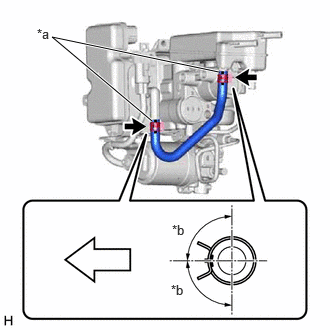
- INSTALL NO. 1 RESERVOIR HOSE
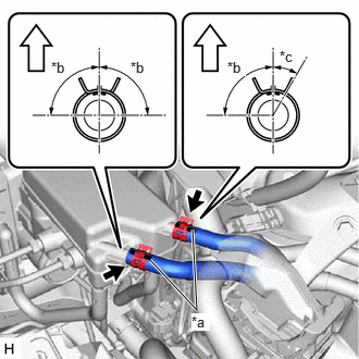
- INSTALL NO. 2 RESERVOIR HOSE
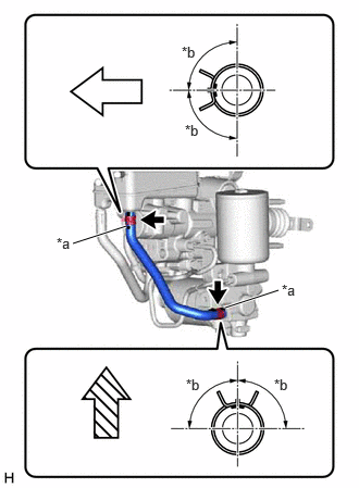
- Install the No. 2 reservoir hose, and slide the 2 clips to secure it.
*a Paint Mark *b 90° 
Front of the Vehicle 
Up NOTE:- Make sure that the paint mark is facing the front of the vehicle (Upper Side).
- Make sure that the paint mark is facing up (Lower Side).
- Install the clip within the range shown in the illustration.
- Install the No. 2 reservoir hose, and slide the 2 clips to secure it.
- INSTALL BRAKE BOOSTER GASKET
- Install a new brake booster gasket to the brake master cylinder with pump assembly.
- INSTALL BRAKE MASTER CYLINDER WITH PUMP ASSEMBLY
- Install the brake master cylinder with pump assembly with the 4 nuts.
Torque: 12.7 N.m (130 kgf/cm, 9 ft.lbf)
NOTE:- Do not apply excessive force to the brake lines.
- Be careful not to allow brake fluid to enter the connector.
- If installing a new brake master cylinder with pump assembly, do not remove the hole plugs before connecting the brake lines because the brake booster with master cylinder assembly is filled with brake fluid.
- Install the brake master cylinder with pump assembly with the 4 nuts.
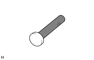
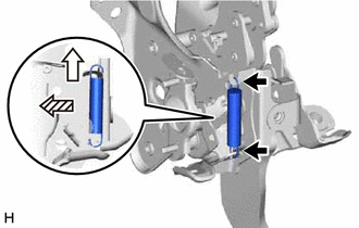
- INSTALL PUSH ROD PIN
- Apply lithium soap base glycol grease to the push rod pin.

Lithium Soap Base Glycol Grease - Connect the master cylinder push rod clevis to the brake pedal support assembly with the push rod pin, and install a new clip as shown in the illustration.
HINT:
The push rod pin can be installed in either direction.
- Apply lithium soap base glycol grease to the push rod pin.
- INSTALL BRAKE PEDAL RETURN SPRING
- Install the brake pedal return spring to the brake pedal support assembly.
Up Front of the Vehicle NOTE:Attach the bottom part of the brake pedal return spring first, making sure that the open part of the hook is facing the front of the vehicle. Attach the top part of the brake pedal return spring second, making sure that the open part of the hook is facing the rear of the vehicle.
- Install the brake pedal return spring to the brake pedal support assembly.
- INSTALL STOP LIGHT SWITCH ASSEMBLY
Refer to PROCEDURE - Step 1
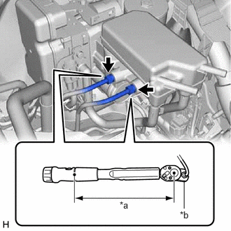
- CONNECT BRAKE LINE
- Using a union nut wrench, connect the 2 brake lines to the brake master cylinder with pump assembly.
Specified tightening torque
Torque: 19.5 N.m (199 kgf/cm, 14 ft.lbf)
NOTE:- Do not kink or damage the brake lines.
- Do not allow the brake lines to twist or interfere with other parts or the vehicle body during tightening.
- Do not allow any foreign matter such as dirt or dust to enter the brake lines from the connecting parts.
HINT:
- Calculate the torque wrench reading when changing the fulcrum length of the torque wrench.
Refer to PRECAUTION [11/2023 - ]
- When using a union nut wrench (fulcrum length of 20 mm (0.787 in.)) + torque wrench (fulcrum length of 162 mm (6.38 in.)):
17.4 N.m (177 kgf/cm, 13 ft.lbf)
*a Torque Wrench Fulcrum Length *b Union Nut Wrench
- Using a union nut wrench, connect the 2 brake lines to the brake master cylinder with pump assembly.
- CONNECT RESERVOIR HOSE
- CONNECT ENGINE ROOM MAIN WIRE
- Install the engine room main wire to the vehicle body with the bolt.
Torque: 8.0 N.m (82 kgf/cm, 71 in.lbf)
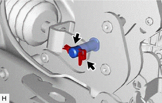
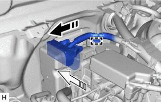
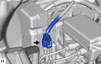
- Engage the clamp to the brake master cylinder with pump assembly.

Connect the connector 
Lock the lock lever - Connect the connector to the brake master cylinder with pump assembly and lock the lock lever.NOTE:
- Make sure that the connector is locked securely.
- Make sure that the connector can be connected smoothly.
- Do not allow water, oil or dirt to enter the connector.
- Connect the connector to the brake master cylinder with pump assembly.NOTE:
Do not allow water, oil or dirt to enter the connector.
- Install the engine room main wire to the vehicle body with the bolt.
- FILL RESERVOIR WITH BRAKE FLUID
- INSTALL VEHICLE APPROACHING SPEAKER CONTROLLER
Refer to PROCEDURE - Step 1
- INSTALL LOWER NO. 1 INSTRUMENT PANEL AIRBAG ASSEMBLY
Refer to PROCEDURE - Step 1
- INSTALL NO. 1 SWITCH HOLE BASE
Refer to PROCEDURE - Step 25
- INSTALL LOWER INSTRUMENT PANEL FINISH PANEL SUB-ASSEMBLY
Refer to PROCEDURE - Step 26
- CONNECT HOOD LOCK CONTROL LEVER SUB-ASSEMBLY
Refer to PROCEDURE - Step 27
- INSTALL ECM
Refer to INSTALLATION [11/2023 - ]
- CONNECT CABLE TO NEGATIVE AUXILIARY BATTERY TERMINAL
Refer to INSTALLATION [11/2023 - ]
- UPDATE ECU SECURITY KEY
HINT:
Perform this procedure only when replacement of the brake booster with master cylinder assembly is necessary.
Refer to UPDATE ECU SECURITY KEY [11/2023 - ]
- BLEED BRAKE SYSTEM
See step 3
- INSPECT AND ADJUST BRAKE PEDAL
Refer to ADJUSTMENT [10/2022 - ]
- INSTALL NO. 1 INSTRUMENT PANEL UNDER COVER SUB-ASSEMBLY
Refer to PROCEDURE - Step 28
- INSTALL COWL SIDE TRIM SUB-ASSEMBLY LH
Refer to PROCEDURE - Step 49
- INSTALL FRONT DOOR SCUFF PLATE LH
Refer to PROCEDURE - Step 50
- INSTALL COWL VENTILATOR PANEL SUB-ASSEMBLY
Refer to PROCEDURE - Step 15
- INSTALL FRONT UPPER SUSPENSION TO COWL BRACE SUB-ASSEMBLY LH
Refer to PROCEDURE - Step 16
- INSTALL FRONT UPPER SUSPENSION TO COWL BRACE SUB-ASSEMBLY RH
HINT:
Perform the same procedure as for the LH side.
- INSTALL FRONT FENDER SPLASH SHIELD SEAL FRONT LH
Refer to PROCEDURE - Step 18
- INSTALL FRONT FENDER SPLASH SHIELD SEAL FRONT RH
HINT:
Perform the same procedure as for the LH side.
- INSTALL FENDER SPLASH SHIELD SUB-ASSEMBLY REAR LH
Refer to PROCEDURE - Step 20
- INSTALL FENDER SPLASH SHIELD SUB-ASSEMBLY REAR RH
HINT:
Perform the same procedure as for the LH side.
- INSTALL WINDSHIELD WIPER MOTOR AND LINK ASSEMBLY
Refer to INSTALLATION [12/2019 - ]
- PERFORM INITIALIZATION AND CALIBRATION
for Electronically Controlled Brake System: Refer to UTILITY [11/2023 - ]
- CHECK AND CLEAR DTC
Refer to DTC CHECK / CLEAR [12/2019 - ]
- INSPECT SRS WARNING LIGHT
Refer to OPERATION CHECK [11/2023 - ]
- INITIALIZATION AFTER RECONNECTING AUXILIARY BATTERY TERMINAL
HINT:
When disconnecting and reconnecting the auxiliary battery, there is an automatic learning function that completes learning when the respective system is used.