Removal [11/2023 - ]: Procedure
WARNING: This page is about a different variant/trim than selected.
- REMOVE FUEL (ENGINE ROOM SIDE) PUMP ASSEMBLY (for High Pressure)
Refer to REMOVAL [11/2023 - ]
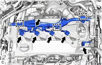
- DISCONNECT ENGINE WIRE
- REMOVE IGNITION COIL ASSEMBLY
Refer to PROCEDURE - Step 2
- REMOVE CAMSHAFT POSITION SENSOR (for Intake Side)
Refer to PROCEDURE - Step 2
- REMOVE CAMSHAFT POSITION SENSOR (for Exhaust Side)
Refer to PROCEDURE - Step 3
- SEPARATE NO. 2 EARTH WIRE
Refer to PROCEDURE - Step 2
- REMOVE CAM TIMING OIL CONTROL SOLENOID ASSEMBLY
Refer to PROCEDURE - Step 3
- REMOVE CAMSHAFT TIMING OIL CONTROL VALVE ASSEMBLY (EXHAUST CAMSHAFT TIMING GEAR BOLT ASSEMBLY)
Refer to PROCEDURE - Step 2
- REMOVE CAM TIMING CONTROL MOTOR WITH EDU ASSEMBLY
Refer to PROCEDURE - Step 6
- REMOVE CAM TIMING CONTROL MOTOR O-RING
Refer to PROCEDURE - Step 7
- REMOVE CYLINDER HEAD COVER SUB-ASSEMBLY
Refer to PROCEDURE - Step 25
- REMOVE SPARK PLUG TUBE GASKET
Refer to PROCEDURE - Step 26
- REMOVE FUEL PUMP LIFTER GUIDE
Refer to PROCEDURE - Step 42
- SET NO. 1 CYLINDER TO TDC (COMPRESSION)
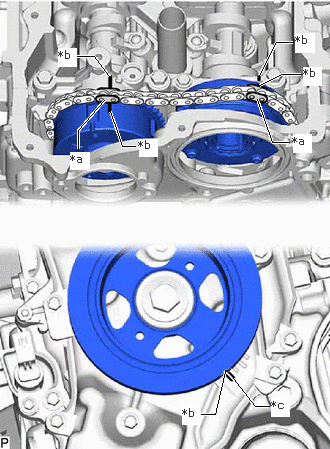
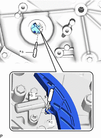
- Turn the crankshaft clockwise to align the timing mark (cutout) on the crankshaft pulley assembly with the "0" timing mark on the No. 2 timing chain cover assembly.
*a Paint Mark *b Timing Mark *c "0" Timing Mark - Check that the timing marks are positioned as shown in the illustration.
HINT:
If the timing marks are not positioned as shown in the illustration, turn the crankshaft clockwise and then align them again.
- Place paint marks on the chain sub-assembly at points aligned with the timing marks on the camshaft timing gear assembly and camshaft timing exhaust gear assembly.
- Turn the crankshaft clockwise to align the timing mark (cutout) on the crankshaft pulley assembly with the "0" timing mark on the No. 2 timing chain cover assembly.
- REMOVE STRAIGHT SCREW PLUG
Refer to PROCEDURE - Step 28
- REMOVE CAMSHAFT
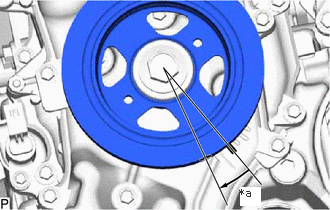
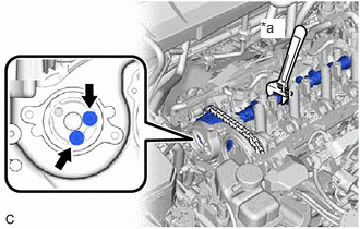
- Rotate the crankshaft approximately 15° clockwise.
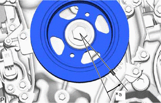
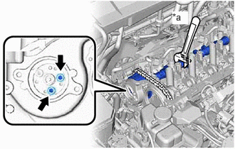
*a Approximately 15° - Rotate the crankshaft approximately 15° counterclockwise.
*a Approximately 15° - Align the pin hole of the No. 1 chain tensioner assembly with the pin hole of the chain tensioner slipper, and then insert the pin.
*a Pin *b Pin Hole (No. 1 Chain Tensioner Assembly Side) *c Pin Hole (Chain Tensioner Slipper Side) - Type A:
- Type B:
- Using the hexagonal portion of the camshaft, hold the camshaft.
*a Hold 
Turn NOTE:- Do not damage the camshaft housing sub-assembly, cylinder head sub-assembly and spark plug tube.
- Do not disassemble the camshaft timing gear assembly.
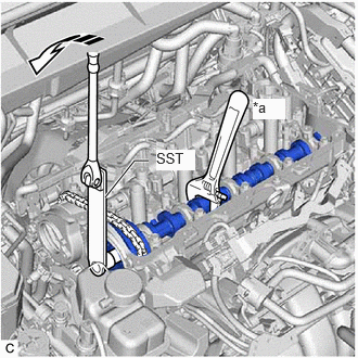
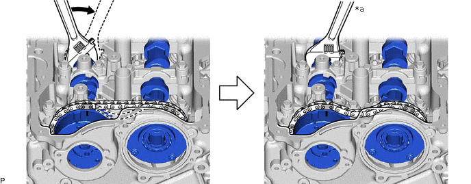
- Using SST and a 10 mm bi-hexagon socket wrench, remove the bolt from the camshaft timing gear assembly.
- SST: 09961-01270
- Using the hexagonal portion of the No. 2 camshaft, loosen and hold the chain sub-assembly while moving the No. 2 camshaft in the direction shown in the illustration.
*a Hold - - 
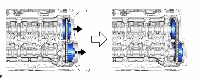
Turn - - - Move the camshaft timing gear assembly together with the camshaft timing exhaust gear assembly and chain sub-assembly toward the No. 2 timing chain cover assembly as shown in the illustration.
*1 Camshaft Timing Gear Assembly *2 Camshaft Timing Exhaust Gear Assembly *3 Chain Sub-assembly - - Remove in this Direction - - - Remove the camshaft timing exhaust gear assembly from the chain sub-assembly.
- Remove the camshaft timing gear assembly from the chain sub-assembly.
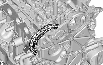
- Secure the chain sub-assembly to the vehicle using rope, etc.NOTE:
Do not drop the chain sub-assembly into the timing chain cover assembly.
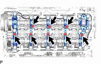
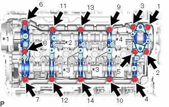
- Uniformly loosen and remove the 8 bolts in the order shown in the illustration.
- Uniformly loosen and remove the 14 bolts in the order shown in the illustration.NOTE:
Uniformly loosen the bolts while holding the camshaft horizontally.
*1 No. 1 Camshaft Bearing Cap *2 No. 2 Camshaft Bearing Cap *3 No. 3 Camshaft Bearing Cap *4 No. 4 Camshaft Bearing Cap - Remove the No. 1 camshaft bearing cap, No. 2 camshaft bearing cap, 2 No. 3 camshaft bearing caps and No. 4 camshaft bearing cap.
HINT:
Arrange the removed parts so that they can be reinstalled in their original locations.
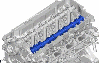
- Remove the camshaft from the camshaft housing sub-assembly.
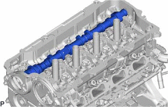
- Remove the No. 2 camshaft from the camshaft housing sub-assembly.
- Rotate the crankshaft approximately 15° clockwise.