Installation [11/2023 - ]: Procedure
- INSTALL PORT FUEL INJECTOR ASSEMBLY
HINT:
Perform "Inspection After Repair" after replacing a port fuel injector assembly.
Refer to INITIALIZATION [10/2021 - ]
- Apply a light coat of spindle oil or gasoline to 4 new O-rings, and install one to each port fuel injector assembly.NOTE:
Check that there is no damage or foreign matter on the groove of the port fuel injector assembly when installing the O-ring to each port fuel injector assembly.
- Install the 4 port fuel injector assemblies to the fuel delivery pipe sub-assembly.
*a Stopper *b Claw NOTE:- Make sure that the port fuel injector assembly is located within the stopper as shown in the illustration.
- Check that the port fuel injector assembly installation holes of the fuel delivery pipe sub-assembly are not damaged and are free of foreign matter.
- Make sure that the O-ring is not damaged, twisted or moved out of place when installing the port fuel injector assembly.
- Apply a light coat of spindle oil or gasoline to 4 new O-rings, and install one to each port fuel injector assembly.
- INSTALL NO. 5 ENGINE WIRE
- Engage the 2 clamps to install the No. 5 engine wire to the fuel delivery pipe sub-assembly.
- Connect the 4 port fuel injector assembly connectors and No. 2 fuel pressure sensor connector.
- INSTALL INJECTOR VIBRATION INSULATOR
- Install 4 new injector vibration insulators to the cylinder head sub-assembly.
- INSTALL NO. 1 DELIVERY PIPE SPACER
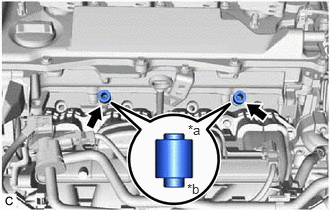
- INSTALL FUEL DELIVERY PIPE SUB-ASSEMBLY
- Place the fuel delivery pipe sub-assembly with the 4 port fuel injector assemblies onto the cylinder head sub-assembly.NOTE:
Be careful not to drop the port fuel injector assemblies when installing the fuel delivery pipe sub-assembly.
- Install the fuel delivery pipe sub-assembly with the port fuel injector assemblies with the 2 bolts.
Torque: 28.5 N.m (291 kgf/cm, 21 ft.lbf)
- Connect the No. 5 engine wire connector.
- Place the fuel delivery pipe sub-assembly with the 4 port fuel injector assemblies onto the cylinder head sub-assembly.
- TEMPORARILY INSTALL FUEL (ENGINE ROOM SIDE) PUMP ASSEMBLY
Refer to PROCEDURE - Step 1
- TEMPORARILY INSTALL NO. 1 FUEL PIPE SUB-ASSEMBLY NOTE:
Do not damage the seals of the union nuts of the No. 1 fuel pipe sub-assembly.
- for Cylinder Head Cover Sub-assembly Connection Type:
- Temporarily install the bolt.
- Temporarily install the No. 1 fuel pipe sub-assembly to the fuel delivery pipe and tighten the union nut by hand.
- Temporarily install the No. 1 fuel pipe sub-assembly to the fuel pump assembly and tighten the union nut by hand.
- for Cylinder Head Cover Sub-assembly Connection Type:
- INSTALL FUEL (ENGINE ROOM SIDE) PUMP ASSEMBLY
Refer to PROCEDURE - Step 3
- INSTALL NO. 1 FUEL PIPE SUB-ASSEMBLY
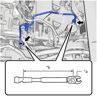
- for EGR Valve Bracket Connection Type:
- Using a 17 mm union nut wrench, tighten the union nut on the fuel delivery pipe side of the No. 1 fuel pipe sub-assembly.
*a 17 mm Union Nut Wrench *b Torque Wrench Fulcrum Length Specified tightening torque
Torque: 35 N.m (357 kgf/cm, 26 ft.lbf)
NOTE:Do not adjust the torque in the loosening direction.
HINT:
- Calculate the torque wrench reading when changing the fulcrum length of the torque wrench.
Refer to PRECAUTION [11/2023 - ]
- When using a 17 mm union nut wrench (fulcrum length of 30 mm (1.18 in.)) + torque wrench (fulcrum length of 180 mm (7.09 in.)): 30 N.m (306 kgf/cm, 22 ft.lbf)
- Calculate the torque wrench reading when changing the fulcrum length of the torque wrench.
- Using a 17 mm union nut wrench, tighten the union nut on the fuel pump assembly side of the No. 1 fuel pipe sub-assembly.
Specified tightening torque
Torque: 35 N.m (357 kgf/cm, 26 ft.lbf)
NOTE:Do not adjust the torque in the loosening direction.
HINT:
- Calculate the torque wrench reading when changing the fulcrum length of the torque wrench.
Refer to PRECAUTION [11/2023 - ]
- When using a 17 mm union nut wrench (fulcrum length of 30 mm (1.18 in.)) + torque wrench (fulcrum length of 180 mm (7.09 in.)): 30 N.m (306 kgf/cm, 22 ft.lbf)
- Calculate the torque wrench reading when changing the fulcrum length of the torque wrench.
- Using a 17 mm union nut wrench, tighten the union nut on the fuel delivery pipe side of the No. 1 fuel pipe sub-assembly.
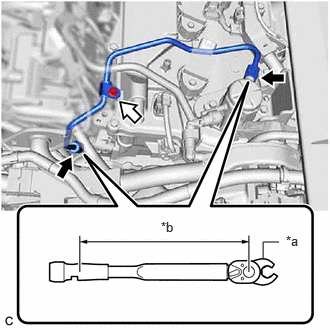
- for Cylinder Head Cover Sub-assembly Connection Type:
- Using a 17 mm union nut wrench, tighten the union nut on the fuel delivery pipe side of the No. 1 fuel pipe sub-assembly.
*a 17 mm Union Nut Wrench *b Torque Wrench Fulcrum Length 
Union Nut 
Bolt Specified tightening torque
Torque: 35 N.m (357 kgf/cm, 26 ft.lbf)
NOTE:Do not adjust the torque in the loosening direction.
HINT:
- Calculate the torque wrench reading when changing the fulcrum length of the torque wrench.
Refer to PRECAUTION [11/2023 - ]
- When using a 17 mm union nut wrench (fulcrum length of 30 mm (1.18 in.)) + torque wrench (fulcrum length of 180 mm (7.09 in.)): 30 N.m (306 kgf/cm, 22 ft.lbf)
- Calculate the torque wrench reading when changing the fulcrum length of the torque wrench.
- Using a 17 mm union nut wrench, tighten the union nut on the fuel pump assembly side of the No. 1 fuel pipe sub-assembly.
Specified tightening torque
Torque: 35 N.m (357 kgf/cm, 26 ft.lbf)
NOTE:Do not adjust the torque in the loosening direction.
HINT:
- Calculate the torque wrench reading when changing the fulcrum length of the torque wrench.
Refer to PRECAUTION [11/2023 - ]
- When using a 17 mm union nut wrench (fulcrum length of 30 mm (1.18 in.)) + torque wrench (fulcrum length of 180 mm (7.09 in.)): 30 N.m (306 kgf/cm, 22 ft.lbf)
- Calculate the torque wrench reading when changing the fulcrum length of the torque wrench.
- Using an 8 mm socket wrench, tighten the bolt.
Torque: 10 N.m (102 kgf/cm, 7 ft.lbf)
- Using a 17 mm union nut wrench, tighten the union nut on the fuel delivery pipe side of the No. 1 fuel pipe sub-assembly.
- Connect the ignition coil connector.
- for EGR Valve Bracket Connection Type:
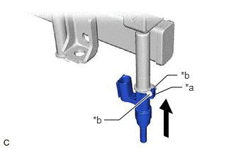
- CONNECT FUEL TUBE SUB-ASSEMBLY
- Connect the fuel tube sub-assembly to the fuel pump assembly and fuel delivery pipe sub-assembly.
Refer to PRECAUTION [11/2023 - ]
- Install the fuel pipe clamp to the fuel tube connector.
- Connect the fuel tube sub-assembly to the fuel pump assembly and fuel delivery pipe sub-assembly.
- INSTALL NO. 2 WATER BY-PASS PIPE
Refer to PROCEDURE - Step 6
- INSTALL EGR VALVE ASSEMBLY
Refer to INSTALLATION [10/2021 - ]
- INSTALL THROTTLE BODY WITH MOTOR ASSEMBLY
Refer to INSTALLATION [09/2020 - ]
- CONNECT CABLE TO NEGATIVE AUXILIARY BATTERY TERMINAL
Refer to PROCEDURE - Step 2
- INSTALL BATTERY SERVICE HOLE COVER
Refer to PROCEDURE - Step 66
- INSPECT FOR FUEL LEAK
Refer to PROCEDURE - Step 1
- PERFORM INITIALIZATION
- Perform "Inspection After Repair" after replacing a port fuel injector assembly.
Refer to INITIALIZATION [10/2021 - ]
- Perform "Inspection After Repair" after replacing a port fuel injector assembly.
- INITIALIZATION AFTER RECONNECTING AUXILIARY BATTERY TERMINAL
HINT:
When disconnecting and reconnecting the auxiliary battery, there is an automatic learning function that completes learning when the respective system is used.