Installation [12/2019 - 10/2021]: Procedure
- INSTALL NO. 3 EXHAUST MANIFOLD HEAT INSULATOR
- Install the No. 3 exhaust manifold heat insulator to the cylinder block sub-assembly with the bolt.
Torque: 16 N.m (163 kgf/cm, 12 ft.lbf)
- Install the No. 3 exhaust manifold heat insulator to the cylinder block sub-assembly with the bolt.
- INSTALL ENGINE OIL LEVEL DIPSTICK GUIDE
- Apply a light coat of engine oil to a new O-ring.
- Install the O-ring to the engine oil level dipstick guide.
- Using an 8 mm socket wrench, install the engine oil level dipstick guide to the camshaft housing sub-assembly with the bolt.
Torque: 10 N.m (102 kgf/cm, 7 ft.lbf)
- Install the engine oil level dipstick.
- INSTALL IGNITION COIL ASSEMBLY
Refer to PROCEDURE - Step 2
- INSTALL DIRECT FUEL INJECTOR ASSEMBLY
Refer to PROCEDURE - Step 2
- INSTALL FUEL DELIVERY PIPE
Refer to PROCEDURE - Step 3
- INSTALL PORT FUEL INJECTOR ASSEMBLY
Refer to PROCEDURE - Step 1
- INSTALL NO. 5 ENGINE WIRE
Refer to PROCEDURE - Step 2
- INSTALL INJECTOR VIBRATION INSULATOR
Refer to PROCEDURE - Step 3
- INSTALL NO. 1 DELIVERY PIPE SPACER
Refer to PROCEDURE - Step 4
- INSTALL FUEL DELIVERY PIPE SUB-ASSEMBLY
Refer to PROCEDURE - Step 5
- INSTALL WIRE HARNESS CLAMP BRACKET
- Using an 8 mm socket wrench, install the wire harness clamp bracket to the No. 1 ventilation case with the 2 bolts.
Torque: 10 N.m (102 kgf/cm, 7 ft.lbf)
- Using an 8 mm socket wrench, install the wire harness clamp bracket to the No. 1 ventilation case with the 2 bolts.
- INSTALL NO. 6 ENGINE WIRE
- Install the No. 6 engine wire to the wire harness clamp bracket with the 2 nuts.
Torque: 10 N.m (102 kgf/cm, 7 ft.lbf)
- Engage the 2 clamps.
- Connect the 4 connectors.
- Install the No. 6 engine wire to the wire harness clamp bracket with the 2 nuts.
- INSTALL SENSOR WIRE
- Using an 8 mm socket wrench, install the sensor wire to the water inlet with thermostat sub-assembly with the bolt.
Torque: 10 N.m (102 kgf/cm, 7 ft.lbf)
- Engage the 3 clamps.
- Connect the 4 connectors.
- Using an 8 mm socket wrench, install the sensor wire to the water inlet with thermostat sub-assembly with the bolt.
- INSTALL NO. 7 WATER BY-PASS HOSE
- Install the No. 7 water by-pass hose and slide the 2 clips to secure it.
- TEMPORARILY INSTALL FUEL (ENGINE ROOM SIDE) PUMP ASSEMBLY (for High Pressure)
Refer to PROCEDURE - Step 1
- TEMPORARILY INSTALL NO. 1 FUEL PIPE SUB-ASSEMBLY
Refer to PROCEDURE - Step 2
- INSTALL FUEL (ENGINE ROOM SIDE) PUMP ASSEMBLY (for High Pressure)
Refer to PROCEDURE - Step 3
- INSTALL NO. 1 FUEL PIPE SUB-ASSEMBLY
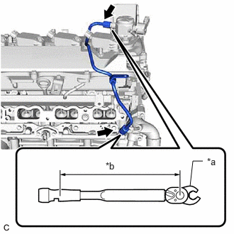
- for EGR Valve Bracket Connection Type:
- Using a 17 mm union nut wrench, tighten the union nut on the fuel delivery pipe side of the No. 1 fuel pipe sub-assembly.
*a 17 mm Union Nut Wrench *b Torque Wrench Fulcrum Length Specified tightening torque
Torque: 35 N.m (357 kgf/cm, 26 ft.lbf)
NOTE:Do not adjust the torque in the loosening direction.
HINT:
- Calculate the torque wrench reading when changing the fulcrum length of the torque wrench.
Refer to PRECAUTION [12/2019 - 11/2023]
- When using a 17 mm union nut wrench (fulcrum length of 30 mm (1.18 in.)) + torque wrench (fulcrum length of 180 mm (7.09 in.)): 30 N.m (306 kgf/cm, 22 ft.lbf)
- Calculate the torque wrench reading when changing the fulcrum length of the torque wrench.
- Using a 17 mm union nut wrench, tighten the union nut on the fuel pump assembly side of the No. 1 fuel pipe sub-assembly.
Specified tightening torque
Torque: 35 N.m (357 kgf/cm, 26 ft.lbf)
NOTE:Do not adjust the torque in the loosening direction.
HINT:
- Calculate the torque wrench reading when changing the fulcrum length of the torque wrench.
Refer to PRECAUTION [12/2019 - 11/2023]
- When using a 17 mm union nut wrench (fulcrum length of 30 mm (1.18 in.)) + torque wrench (fulcrum length of 180 mm (7.09 in.)): 30 N.m (306 kgf/cm, 22 ft.lbf)
- Calculate the torque wrench reading when changing the fulcrum length of the torque wrench.
- Using a 17 mm union nut wrench, tighten the union nut on the fuel delivery pipe side of the No. 1 fuel pipe sub-assembly.
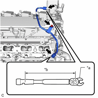
- for Cylinder Head Cover Sub-assembly Connection Type:
- Using a 17 mm union nut wrench, tighten the union nut on the fuel delivery pipe side of the No. 1 fuel pipe sub-assembly.
Specified tightening torque
Torque: 35 N.m (357 kgf/cm, 26 ft.lbf)
NOTE:Do not adjust the torque in the loosening direction.
HINT:
- Calculate the torque wrench reading when changing the fulcrum length of the torque wrench.
Refer to PRECAUTION [12/2019 - 11/2023]
- When using a 17 mm union nut wrench (fulcrum length of 30 mm (1.18 in.)) + torque wrench (fulcrum length of 180 mm (7.09 in.)): 30 N.m (306 kgf/cm, 22 ft.lbf)
*a 17 mm Union Nut Wrench *b Torque Wrench Fulcrum Length - Calculate the torque wrench reading when changing the fulcrum length of the torque wrench.
- Using a 17 mm union nut wrench, tighten the union nut on the fuel pump assembly side of the No. 1 fuel pipe sub-assembly.
Specified tightening torque
Torque: 35 N.m (357 kgf/cm, 26 ft.lbf)
NOTE:Do not adjust the torque in the loosening direction.
HINT:
- Calculate the torque wrench reading when changing the fulcrum length of the torque wrench.
Refer to PRECAUTION [12/2019 - 11/2023]
- When using a 17 mm union nut wrench (fulcrum length of 30 mm (1.18 in.)) + torque wrench (fulcrum length of 180 mm (7.09 in.)): 30 N.m (306 kgf/cm, 22 ft.lbf)
- Calculate the torque wrench reading when changing the fulcrum length of the torque wrench.
- Using an 8 mm socket wrench, install the bolt.
Torque: 10 N.m (102 kgf/cm, 7 ft.lbf)
- Using a 17 mm union nut wrench, tighten the union nut on the fuel delivery pipe side of the No. 1 fuel pipe sub-assembly.
- for EGR Valve Bracket Connection Type:
- CONNECT FUEL TUBE SUB-ASSEMBLY
Refer to PROCEDURE - Step 6
- INSTALL NO. 1 INTAKE MANIFOLD TO HEAD GASKET
Refer to PROCEDURE - Step 3
- INSTALL INTAKE MANIFOLD
Refer to PROCEDURE - Step 4
- INSTALL NO. 2 WATER BY-PASS PIPE
- INSTALL NO. 3 WATER BY-PASS PIPE
- Install the No. 3 water by-pass pipe to the water outlet and slide the clip to secure it.
- Using an 8 mm socket wrench, connect the No. 3 water by-pass pipe to the intake manifold with the bolt.
Torque: 10 N.m (102 kgf/cm, 7 ft.lbf)
- INSTALL EGR VALVE ASSEMBLY
- Using an 8 mm socket wrench, install the EGR valve bracket with the bolt.
Torque: 10 N.m (102 kgf/cm, 7 ft.lbf)
- for EGR Valve Bracket Connection Type:
- Align and fit the hole of the EGR valve bracket to the pin of the camshaft housing sub-assembly.
*a Pin *b Hole - Using the 8 mm socket wrench, install the EGR valve assembly with the EGR valve bracket to the camshaft housing sub-assembly with the bolt.
Torque: 10 N.m (102 kgf/cm, 7 ft.lbf)
- Using the 8 mm socket wrench, connect the No. 1 fuel pipe sub-assembly to the EGR valve bracket with the bolt.
Torque: 10 N.m (102 kgf/cm, 7 ft.lbf)
- Align and fit the hole of the EGR valve bracket to the pin of the camshaft housing sub-assembly.
- for Cylinder Head Cover Sub-assembly Connection Type:
- Connect the No. 8 water by-pass hose to the EGR valve assembly and slide the clip to secure it.
- Using an 8 mm socket wrench, install the EGR valve bracket with the bolt.
- INSTALL NO. 4 WATER BY-PASS HOSE
- Install the No. 4 water by-pass hose to the EGR valve assembly and slide the clip to secure it.
- INSTALL NO. 1 EGR PIPE SUB-ASSEMBLY
Refer to PROCEDURE - Step 2
- INSTALL EGR COOLER ASSEMBLY
- Install the EGR cooler assembly, a new EGR cooler gasket and a new EGR valve gasket with the 5 bolts.
Torque: 24 N.m (245 kgf/cm, 18 ft.lbf)
- Connect the No. 3 water by-pass hose to the EGR cooler assembly and slide the clip to secure it.
- Connect the No. 4 water by-pass hose to the EGR cooler assembly and slide the clip to secure it.
- Install the EGR cooler assembly, a new EGR cooler gasket and a new EGR valve gasket with the 5 bolts.
- INSTALL THROTTLE BODY GASKET
Refer to PROCEDURE - Step 1 [12/2019 - 09/2020] , or refer to PROCEDURE - Step 1 [09/2020 - ]
- INSTALL THROTTLE BODY WITH MOTOR ASSEMBLY
Refer to PROCEDURE - Step 2 [12/2019 - 09/2020] , or refer to PROCEDURE - Step 2 [09/2020 - ]
- INSTALL EXHAUST MANIFOLD (TWC: Front Catalyst)
Refer to PROCEDURE - Step 2
- INSTALL MANIFOLD STAY
Refer to PROCEDURE - Step 3
- INSTALL NO. 1 EXHAUST MANIFOLD HEAT INSULATOR
- Install the No. 1 exhaust manifold heat insulator to the exhaust manifold (TWC: Front Catalyst) with the 5 bolts.
Torque: 10 N.m (102 kgf/cm, 7 ft.lbf)
- Install the No. 1 exhaust manifold heat insulator to the exhaust manifold (TWC: Front Catalyst) with the 5 bolts.
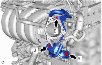
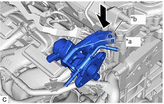
- INSTALL FLOW SHUTTING VALVE (WATER BY-PASS HOSE ASSEMBLY)
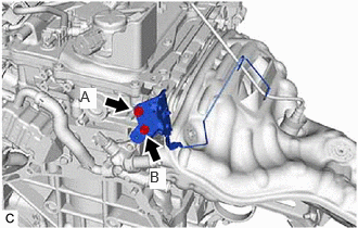
- Install the water hose clamp bracket with the 2 bolts as shown in the illustration.
Torque: 13 N.m (133 kgf/cm, 10 ft.lbf)
NOTE:Temporarily tighten the bolt (A), and then fully tighten the 2 bolts in the order of (B) and (A).
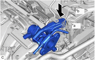
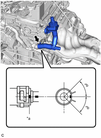
- Connect the flow shutting valve (water by-pass hose assembly) to the water by-pass outlet and slide the clip to secure it.
*a Paint Mark *b 45° (Claw of Clip Location) NOTE:- Make sure to slide the flow shutting valve (water by-pass hose assembly) until it contacts the hose stopper of the water by-pass outlet.
- Make sure that the claws of the clip are within the location shown in the illustration.
- Install the flow shutting valve (water by-pass hose assembly) with the bolt.
Torque: 19 N.m (194 kgf/cm, 14 ft.lbf)
- Install the water hose clamp bracket with the 2 bolts as shown in the illustration.
- INSTALL NO. 2 WATER BY-PASS PIPE SUB-ASSEMBLY
- Install the No. 2 water by-pass pipe sub-assembly with the bolt.
Torque: 19 N.m (194 kgf/cm, 14 ft.lbf)
- Connect the No. 2 water by-pass pipe sub-assembly to the water by-pass outlet and slide the clip to secure it.
- Install the No. 2 water by-pass pipe sub-assembly with the bolt.
- INSTALL COMPRESSOR WITH MOTOR ASSEMBLY
- Using an E8 "TORX" socket wrench, temporarily install the compressor with motor assembly with the 2 stud bolts.
Torque: 4.0 N.m (41 kgf/cm, 35 in.lbf)
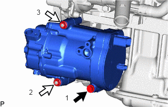
- Install the compressor with motor assembly with the bolt and 2 nuts.
 Courtesy of © TOYOTA, LICENSE AGREEMENT TMS1002
Bolt 
Nut Torque: 24.5 N.m (250 kgf/cm, 18 ft.lbf)
HINT:
Tighten the bolt and nuts in the order shown in the illustration.
- Using an E8 "TORX" socket wrench, temporarily install the compressor with motor assembly with the 2 stud bolts.
- INSTALL DRIVE SHAFT BEARING BRACKET
- Install the drive shaft bearing bracket with the 3 bolts.
Torque: 63.7 N.m (650 kgf/cm, 47 ft.lbf)
- Install the drive shaft bearing bracket with the 3 bolts.