Operation Method [12/2019 - ]: Procedure
- PRECAUTION
Refer to PRECAUTION [12/2019 - ]
- REMOVE FRONT DOOR SCUFF PLATE LH
Refer to PROCEDURE - Step 9 [12/2019 - 10/2022] , or refer to PROCEDURE - Step 9 [10/2022 - ]
- REMOVE FRONT DOOR SCUFF PLATE RH
HINT:
Use the same procedure as for the LH side.
- REMOVE COWL SIDE TRIM SUB-ASSEMBLY LH
Refer to PROCEDURE - Step 10 [12/2019 - 10/2022] , or refer to PROCEDURE - Step 10 [10/2022 - ]
- REMOVE COWL SIDE TRIM SUB-ASSEMBLY RH
HINT:
Use the same procedure as for the LH side.
- REMOVE BATTERY SERVICE HOLE COVER (for HV Model)
Refer to PROCEDURE - Step 1 [12/2019 - 10/2022] , or refer to PROCEDURE - Step 1 [10/2022 - 11/2023] , or refer to PROCEDURE - Step 2 [11/2023 - ]
- PARKING BRAKE FORCED RELEASE WARNING:
Work on a level surface to ensure safety.
NOTE:- To release the parking brake, follow the procedure for when using SST.
- If the parking brake cannot be released, follow the procedure for when not using SST.
- When moving the vehicle after releasing the parking brake, install all parts and do not connect the 2 connectors shown in the illustration.
- If the ignition switch is ON or the hybrid system or engine is started with the 2 connectors disconnected, a DTC may be stored. Clear any DTCs after performing work.
for HV Model: Refer to DTC CHECK / CLEAR [12/2019 - ]
for Gasoline Model: Refer to DTC CHECK / CLEAR [12/2019 - ]
- When using SST:
- Park the vehicle on a level surface and move the shift lever to P.
- Turn the ignition switch off and use wheel chocks to secure the vehicle.
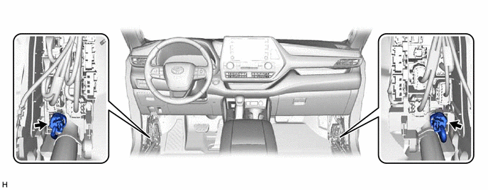
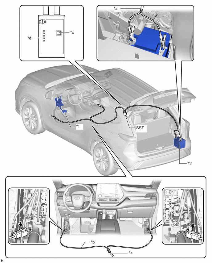
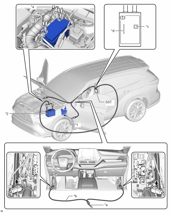
- Disconnect the 2 connectors shown in the illustration.
- Connect SST (09756-48020) to SST (09756-48060).
- SST: 09756-4802009756-48060
for HV Model:
*1 Brake Pedal *2 Auxiliary Battery *a SST (09756-48020) *b SST (09756-48060) *c Release Button *d Finished Light 
Connector - - for Gasoline Model:
*1 Brake Pedal *2 Battery *a SST (09756-48020) *b SST (09756-48060) *c Release Button *d Finished Light Connector - - - Connect SST (09756-48060) to the 2 connectors.
- Connect SST (09756-48020) to the auxiliary battery.
- Push the release button on SST (09756-48020) with the brake pedal depressed.WARNING:
The vehicle may suddenly move when the parking brake is released. Make sure to perform the release operation with the brake pedal depressed.
HINT:
- Confirm that the parking brake is operating by listening for operation sounds.
- If no operation sounds are heard, push the release button on SST (09756-48020) with the brake pedal depressed.
- The parking brake may not release if the auxiliary battery voltage is too low. In this case, perform the release operation again using a fully charged or new auxiliary battery.
- When the finished light of SST (09756-48020) illuminates, release the brake pedal.
- Move the vehicle forward and rearward to check that the parking brake is released.WARNING:
Be careful when performing this operation. The vehicle may suddenly move.
NOTE:When moving the vehicle after releasing the parking brake, check that the 2 connectors are disconnected.
- When not using SST:NOTE:
Perform the following procedure only when the parking brake cannot be released using SST.
HINT:
- Use the same procedure for the RH side and LH side.
- The following procedure is for the LH side.
- Park the vehicle on a level surface and check that the shift lever is in P.
- Turn the ignition switch off and use wheel chocks to secure the vehicle.
- Check that the 2 connectors shown in the illustration have been disconnected.
- Remove the rear wheel.
Refer to REMOVAL [12/2019 - 10/2022] , or refer to REMOVAL [10/2022 - ]
WARNING:When using a jack to lift the vehicle, make sure to support the vehicle using safety stands. Do not work on the vehicle with it supported only by a jack.
- Disconnect the No. 2 parking brake wire assembly connector from the parking brake actuator assembly.
See step 4
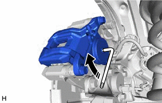
- Remove the parking brake actuator assembly from the rear disc brake cylinder assembly.
See step 5
- Insert an L-shaped T45 "TORX" wrench into the rear disc brake cylinder assembly.
- Turn the L-shaped T45 "TORX" wrench 2 full rotations clockwise to release the parking brake lock.
- INSTALL BATTERY SERVICE HOLE COVER (for HV Model)
Refer to PROCEDURE - Step 3 [12/2019 - 11/2023] , or refer to PROCEDURE - Step 3 [11/2023 - ]
- INSTALL COWL SIDE TRIM SUB-ASSEMBLY LH
Refer to PROCEDURE - Step 51 [12/2019 - 10/2022] , or refer to PROCEDURE - Step 49 [10/2022 - ]
- INSTALL COWL SIDE TRIM SUB-ASSEMBLY RH
HINT:
Use the same procedure as for the LH side.
- INSTALL FRONT DOOR SCUFF PLATE LH
Refer to PROCEDURE - Step 52 [12/2019 - 10/2022] , or refer to PROCEDURE - Step 50 [10/2022 - ]
- INSTALL FRONT DOOR SCUFF PLATE RH
HINT:
Use the same procedure as for the LH side.