DTC P0171-00: System Too Lean Bank 1; DTC P0172-00: System Too Rich Bank 1; DTC P1170-00: Fuel Performance/Port Injector; DTC P117B-00: Fuel Performance/Direct Injector [10/2022 - 11/2023]: Procedure
- CHECK ANY OTHER DTCS OUTPUT (IN ADDITION TO DTC P0171-00, P0172-00, P1170-00 AND/OR P117B-00)
- Read the DTCs.
Powertrain > Engine > Trouble Codes
Result
Result Proceed to DTC P0171-00, P0172-00, P1170-00 and/or P117B-00 is output A DTC P0171-00, P0172-00, P1170-00 and/or P117B-00 and other DTCs are output B HINT:
If any DTCs other than P0171-00, P0172-00, P1170-00 and/or P117B-00 are output, troubleshoot those DTCs first.
Result:
B
GO TO DTC CHART . Refer to DIAGNOSTIC TROUBLE CODE CHART [10/2022 - 11/2023]
Result:
A
See step 2
- Read the DTCs.
- PERFORM ACTIVE TEST USING GTS (CONTROL THE INJECTION MODE)
- Put the engine in Inspection Mode (Maintenance Mode).
Powertrain > Hybrid Control > Utility
Tester Display Inspection Mode - Start the engine and warm it up until the engine coolant temperature is 75°C (167°F) or higher with all the accessories switched off.
Powertrain > Engine > Data List
Tester Display Coolant Temperature - According to the display on the GTS, read the Data List with the Active Test "Control the Injection Mode" set to Port.
Powertrain > Engine > Active Test
Active Test Display Control the Injection Mode Data List Display Injection Mode Short FT B1S1 Long FT B1S1 OK
GTS Display Specified Condition Total of Short FT B1S1 and Long FT B1S1 Between -20 and 20% - According to the display on the GTS, read the Data List with the Active Test "Control the Injection Mode" set to Direct.
Powertrain > Engine > Active Test
Active Test Display Control the Injection Mode Data List Display Injection Mode Short FT B1S1 Long FT B1S1 OK
GTS Display Specified Condition Total of Short FT B1S1 and Long FT B1S1 Between -20 and 20% Result
Item Proceed to Port Direct OK OK A OK NG B NG OK C NG NG D
Result:
B
See step 4
Result:
C
See step 11
Result:
D
See step 12
Result:
A
See step 3
- Put the engine in Inspection Mode (Maintenance Mode).
- CHECK IF VEHICLE HAS RUN OUT OF FUEL IN PAST
Result:
YES
DTC CAUSED BY RUNNING OUT OF FUEL
Result:
NO
CHECK FOR INTERMITTENT PROBLEMS
- READ VALUE USING GTS (FUEL PRESSURE (HIGH))
- Put the engine in Inspection Mode (Maintenance Mode).
Powertrain > Hybrid Control > Utility
Tester Display Inspection Mode - Start the engine and warm it up until the engine coolant temperature is 75°C (167°F) or higher with all the accessories switched off.
Powertrain > Engine > Data List
Tester Display Coolant Temperature - According to the display on the GTS, read the Data List.
Powertrain > Engine > Data List
Tester Display Engine Speed Fuel Pressure (High) Injection Mode HINT:
During charge control, the engine speed is set at idle. Therefore, the engine speed will not increase when the accelerator pedal is depressed. In this case, read the Data List after charge control has completed.
Standard
GTS Display Condition Specified Condition Fuel Pressure (High) - Shift position: P
- A/C: Off
- Engine warmed up
- Engine Speed: 2500 rpm
- Injection Mode: Direct
3000 to 25000 kPa Result
Proceed to OK NG
Result:
NG
See step 7
Result:
OK
See step 5
- Put the engine in Inspection Mode (Maintenance Mode).
- PERFORM ACTIVE TEST USING GTS (CONTROL THE INJECTION MODE (DIRECT))
- Put the engine in Inspection Mode (Maintenance Mode).
Powertrain > Hybrid Control > Utility
Tester Display Inspection Mode - Start the engine and warm it up until the engine coolant temperature is 75°C (167°F) or higher with all the accessories switched off.
Powertrain > Engine > Data List
Tester Display Coolant Temperature - According to the display on the GTS, read the Data List with the Active Test "Control the Injection Mode" set to Direct.
Powertrain > Engine > Active Test
Active Test Display Control the Injection Mode Data List Display High Pressure Fuel Pump Duty Ratio (D4) Injection Mode Short FT B1S1 Long FT B1S1 HINT:
The A/C switch and all accessory switches should be off, and the shift lever should be in the P position, and the engine should be fully warmed up.
Result
Item Proceed to Injection Mode High Pressure Fuel Pump Duty Ratio (D4) Total of Short FT B1S1 and Long FT B1S1 Direct 10 to 50% - A 50% or higher -20% or less B 10% or less +20% or higher 50% or higher +20% or higher C 10% or less -20% or less D HINT:
Perform "Inspection After Repair" after replacing the fuel pressure sensor (for high pressure side).
Refer to INITIALIZATION [10/2021 - ]
Result:
B
REPLACE FUEL PRESSURE SENSOR (FOR HIGH PRESSURE SIDE)
Refer to REMOVAL [10/2022 - 11/2023]
Result:
C
See step 8
Result:
D
REPLACE ECM
Refer to REMOVAL [10/2022 - 11/2023]
Result:
A
See step 6
- Put the engine in Inspection Mode (Maintenance Mode).
- PERFORM ACTIVE TEST USING GTS (CONTROL THE INJECTION MODE (DIRECT))
- Put the engine in Inspection Mode (Maintenance Mode).
Powertrain > Hybrid Control > Utility
Tester Display Inspection Mode - Start the engine and warm it up until the engine coolant temperature is 75°C (167°F) or higher with all the accessories switched off.
Powertrain > Engine > Data List
Tester Display Coolant Temperature - According to the display on the GTS, read the Data List with the Active Test "Control the Injection Mode" set to Direct.
Powertrain > Engine > Active Test
Active Test Display Control the Injection Mode Data List Display High Pressure Fuel Pump Duty Ratio (D4) Injection Mode Short FT B1S1 Long FT B1S1 HINT:
The A/C switch and all accessory switches should be off, and the shift lever should be in the P position, and the engine should be fully warmed up.
Result
Item Proceed to Injection Mode High Pressure Fuel Pump Duty Ratio (D4) Total of Short FT B1S1 and Long FT B1S1 Direct 10 to 50% -25% or less A 10 to 50% +25% or higher 10 to 50% -25 to +25% B HINT:
Perform "Inspection After Repair" after replacing the direct fuel injector assembly.
Refer to INITIALIZATION [10/2021 - ]
Result:
A
REPLACE DIRECT FUEL INJECTOR ASSEMBLY
Refer to REMOVAL [10/2022 - 11/2023]
Result:
B
CHECK FOR INTERMITTENT PROBLEMS
- Put the engine in Inspection Mode (Maintenance Mode).
- CHECK MISFIRE COUNT OF DIRECT INJECTION
- Put the engine in Inspection Mode (Maintenance Mode).
Powertrain > Hybrid Control > Utility
Tester Display Inspection Mode - Start the engine and warm it up until the engine coolant temperature is 75°C (167°F) or higher with all the accessories switched off.
Powertrain > Engine > Data List
Tester Display Coolant Temperature - According to the display on the GTS, read the Data List with the Active Test "Control the Injection Mode" set to Direct.
Powertrain > Engine > Active Test
Active Test Display Control the Injection Mode Data List Display Injection Mode Misfire Count Cylinder #1 Misfire Count Cylinder #2 Misfire Count Cylinder #3 Misfire Count Cylinder #4 HINT:
The A/C switch and all accessory switches should be off, and the shift lever should be in the P position, and the engine should be fully warmed up.
Result
Injection Mode Misfire Count Proceed to Direct No misfire counts, or misfire counts occur randomly in all cylinders A Misfire counts occur in particular cylinder B HINT:
Perform "Inspection After Repair" after replacing the direct fuel injector assembly.
Refer to INITIALIZATION [10/2021 - ]
Result:
B
REPLACE DIRECT FUEL INJECTOR ASSEMBLY
Refer to REMOVAL [10/2022 - 11/2023]
Result:
A
See step 8
- Put the engine in Inspection Mode (Maintenance Mode).
- REPLACE FUEL (ENGINE ROOM SIDE) PUMP ASSEMBLY (FOR HIGH PRESSURE SIDE)
Refer to REMOVAL [10/2022 - 11/2023]
HINT:
Perform "Inspection After Repair" after replacing the fuel pump assembly (for high pressure side).
Refer to INITIALIZATION [10/2021 - ]
Result
Proceed to NEXT Result:
NEXT
See step 9
- CLEAR DTC
- Clear the DTCs.
Powertrain > Engine > Clear DTCs
- Turn the ignition switch off and wait for at least 30 seconds.
Result
Proceed to NEXT
Result:
NEXT
See step 10
- Clear the DTCs.
- CONFIRM WHETHER MALFUNCTION HAS BEEN SUCCESSFULLY REPAIRED
- Drive the vehicle in accordance with the driving pattern described in Confirmation Driving Pattern.
- Read the DTCs.
Powertrain > Engine > Trouble Codes
Result
Result Proceed to DTCs are not output A DTC P0171-00, P0172-00, P1170-00 and/or P117B-00 is output B
Result:
A
END
Result:
B
REPLACE ECM
Refer to REMOVAL [10/2022 - 11/2023]
- INSPECT PORT FUEL INJECTOR ASSEMBLY
- Check the injection volume (whether fuel volume is high or low, and whether injection pattern is poor).
Refer to INSPECTION [12/2019 - ]
HINT:
Perform "Inspection After Repair" after replacing the port fuel injector assembly.
Refer to INITIALIZATION [10/2021 - ]
Result
Proceed to OK NG
Result:
OK
REPLACE ECM
Refer to REMOVAL [10/2022 - 11/2023]
Result:
NG
REPLACE PORT FUEL INJECTOR ASSEMBLY
Refer to REMOVAL [10/2022 - 11/2023]
- Check the injection volume (whether fuel volume is high or low, and whether injection pattern is poor).
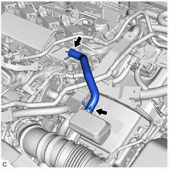
- CHECK PCV VALVE AND HOSE CONNECTIONS
- Check the PCV hose connections.
- Check the PCV valve.
Refer to INSPECTION [12/2019 - ]
OK
PCV hose and PCV valve are connected correctly and are not damaged.
Result
Proceed to OK NG
Result:
NG
REPAIR OR REPLACE PCV VALVE OR HOSE
Result:
OK
See step 13
- CHECK INTAKE SYSTEM
- Check the intake system for vacuum leaks.
Refer to ON-VEHICLE INSPECTION [12/2019 - ]
OK
No leaks in intake system.
HINT:
Perform "Inspection After Repair" after repairing or replacing the intake system.
Refer to INITIALIZATION [10/2021 - ]
Result
Proceed to OK NG
Result:
NG
REPAIR OR REPLACE INTAKE SYSTEM
Result:
OK
See step 14
- Check the intake system for vacuum leaks.
- PERFORM ACTIVE TEST USING GTS (CONTROL THE INJECTION VOLUME FOR A/F SENSOR)
- Put the engine in Inspection Mode (Maintenance Mode).
Powertrain > Hybrid Control > Utility
Tester Display Inspection Mode - Start the engine and warm it up until the engine coolant temperature reaches 75°C (167°F) or higher.
Powertrain > Engine > Data List
Tester Display Coolant Temperature - Idle the engine for 5 minutes or more with the shift lever in P.
- Perform the Control the Injection Volume for A/F Sensor operation with the engine idling.
Powertrain > Engine > Active Test
Active Test Display Control the Injection Volume for A/F Sensor Data List Display A/F (O2) Sensor Current B1S1 A/F (O2) Sensor Current B1S2 - Monitor the output values of the air fuel ratio sensor (sensor 1) and air fuel ratio sensor (sensor 2) (A/F (O2) Sensor Current B1S1 and A/F (O2) Sensor Current B1S2) displayed on the GTS.
HINT:
- The Control the Injection Volume for A/F Sensor operation lowers the fuel injection volume by 12.5% or increases the injection volume by 12.5%.
- The air fuel ratio sensor (sensor 1) has an output delay of a few seconds and the air fuel ratio sensor (sensor 2) has a maximum output delay of approximately 20 seconds.
- If the sensor output value does not change (almost no reaction) while performing the Active Test, the sensor may be malfunctioning.
Standard
GTS Display (Sensor) Injection Volume Status Voltage A/F (O2) Sensor Current B1S1
(Air fuel ratio (sensor 1))12.5% Rich Below -0.075 mA -12.5% Lean More than 0.037 mA A/F (O2) Sensor Current B1S2
(Air fuel ratio (sensor 2))12.5% Rich Below -0.86 mA -12.5% Lean More than 0.33 mA Result
Status A/F (O2) Sensor Current B1S1 Status A/F (O2) Sensor Current B1S2 Air Fuel Ratio Condition and Air Fuel Ratio Sensor Condition Suspected Trouble Area Proceed to Lean/Rich Lean/Rich Normal - A Lean Lean Actual air fuel ratio lean - PCV valve and hose
- PCV hose connections
- Gas leak from exhaust system
- Intake system
- Fuel pressure
- Mass air flow meter sub-assembly
- Engine coolant temperature sensor
- EGR valve assembly
Rich Rich Actual air fuel ratio rich - Gas leak from exhaust system
- Ignition system
- Fuel pressure
- Mass air flow meter sub-assembly
- Engine coolant temperature sensor
- EGR valve assembly
Lean Lean/Rich Air fuel ratio sensor (sensor 1) malfunction - Air fuel ratio sensor (sensor 1)
B Rich Lean/Rich Air fuel ratio sensor (sensor 1) malfunction - Air fuel ratio sensor (sensor 1)
- Lean: During the Control the Injection Volume for A/F Sensor Active Test, the air fuel ratio sensor (sensor 1) output current (A/F (O2) Sensor Current B1S1) is consistently more than 0.037 mA, and the air fuel ratio sensor (sensor 2) output current (A/F (O2) Sensor Current B1S2) is consistently more than 0.33 mA.
- Rich: During the Control the Injection Volume for A/F Sensor Active Test, the air fuel ratio sensor (sensor 1) output current (A/F (O2) Sensor Current B1S1) is consistently below -0.075 mA, and the air fuel ratio sensor (sensor 2) output current (A/F (O2) Sensor Current B1S2) is consistently below -0.86 mA.
- Lean/Rich: During the Control the Injection Volume for A/F Sensor Active Test, the output current of the air fuel ratio sensor (sensor 1) or air fuel ratio sensor (sensor 2) alternate correctly.
HINT:
Refer to "Data List / Active Test" [A/F (O2) Sensor Current B1S1 and A/F (O2) Sensor Current B1S2].
Result:
B
See step 24
Result:
A
See step 15
- Put the engine in Inspection Mode (Maintenance Mode).
- READ VALUE USING GTS (COOLANT TEMPERATURE)
- Read the Data List twice, when the engine is both cold and warmed up.
Powertrain > Engine > Data List
Tester Display Coolant Temperature Standard
GTS Display Condition Specified Condition Coolant Temperature Cold engine Same as ambient air temperature Warm engine Between 75 and 100°C (167 and 212°F) HINT:
Perform "Inspection After Repair" after replacing the engine coolant temperature sensor.
Refer to INITIALIZATION [10/2021 - ]
Result
Proceed to OK NG
Result:
NG
REPLACE ENGINE COOLANT TEMPERATURE SENSOR
Refer to REMOVAL [10/2022 - 11/2023]
Result:
OK
See step 16
- Read the Data List twice, when the engine is both cold and warmed up.
- PERFORM ACTIVE TEST USING GTS (CONTROL THE EGR STEP POSITION)
- Put the engine in Inspection Mode (Maintenance Mode).
Powertrain > Hybrid Control > Utility
Tester Display Inspection Mode - Start the engine and warm it up until the engine coolant temperature reaches 75°C (167°F) or higher.
Powertrain > Engine > Data List
Tester Display Coolant Temperature HINT:
The A/C switch and all accessories should be off.
- Confirm that the value of Data List item Engine Independent is "Operate" then check the value of Intake Manifold Absolute Pressure while performing the Active Test.
Powertrain > Engine > Active Test
Active Test Display Control the EGR Step Position Data List Display Intake Manifold Absolute Pressure Engine Independent NOTE:- Do not leave the EGR valve open for 10 seconds or more during the Active Test.
- Be sure to return the EGR valve to step 0 when the Active Test is completed.
- Do not open the EGR valve 30 steps or more during the Active Test.
OK
The value of Intake Manifold Absolute Pressure changes in response to the EGR step position when the value of Engine Independent is "Operate".
Standard
- Control the EGR Step Position (Active Test) 0 Steps 0 to 30 Steps Intake Manifold Absolute Pressure
(Data List)(EGR valve is fully closed) Intake Manifold Absolute Pressure value is at least +10 kPa (1.45 psi) higher than when EGR valve is fully closed HINT:
- If the value of Data List item Engine Independent is "Not Opr" when the engine is idling, charge control is being performed. Perform the Active Test after charge control is complete ("Operate" is displayed).
- While performing the Active Test, if the increase in the value of Intake Manifold Absolute Pressure is small, the EGR valve assembly may be malfunctioning.
- Even if the EGR valve assembly is malfunctioning, rough idling or an increase in the value of Intake Manifold Absolute Pressure may occur while performing the Active Test. However, the amount that the value of Intake Manifold Absolute Pressure increases will be smaller than normal.
Result
Proceed to OK NG
Result:
OK
See step 18
Result:
NG
See step 17
- Put the engine in Inspection Mode (Maintenance Mode).
- INSPECT EGR VALVE ASSEMBLY
- Remove the EGR valve assembly.
Refer to REMOVAL [10/2022 - 11/2023]
- Check if the EGR valve is stuck open.
OK
EGR valve is tightly closed.
HINT:
Perform "Inspection After Repair" after replacing the EGR valve assembly.
Refer to INITIALIZATION [10/2021 - ]
Result
Proceed to OK NG
Result:
NG
REPLACE EGR VALVE ASSEMBLY
Refer to REMOVAL [10/2022 - 11/2023]
Result:
OK
See step 18
- Remove the EGR valve assembly.
- READ VALUE USING GTS (MASS AIR FLOW SENSOR)
- Put the engine in Inspection Mode (Maintenance Mode).
Powertrain > Hybrid Control > Utility
Tester Display Inspection Mode - Start the engine and warm it up until the engine coolant temperature is 75°C (167°F) or higher with all the accessories switched off.
Powertrain > Engine > Data List
Tester Display Coolant Temperature - Read Mass Air Flow Sensor while maintaining an engine speed of 2500 rpm.
Powertrain > Engine > Data List
Tester Display Engine Speed Mass Air Flow Sensor HINT:
During charge control, the engine speed is set at idle. Therefore, the engine speed will not increase when the accelerator pedal is depressed. In this case, read the Data List after charge control has completed.
Standard
GTS Display Condition Specified Condition Mass Air Flow Sensor - Engine warmed up
- Shift position: P
- A/C: Off
- Engine Speed: 2500 rpm
Between 6.2 and 18.6 gm/sec Result
Proceed to OK NG
Result:
NG
See step 31
Result:
OK
See step 19
- Put the engine in Inspection Mode (Maintenance Mode).
- CHECK FUEL PRESSURE (FOR LOW PRESSURE SIDE)
Refer to PROCEDURE - Step 2
Result
Proceed to OK NG Result:
NG
See step 23
Result:
OK
See step 20
- CHECK FOR EXHAUST GAS LEAK
- Check for exhaust gas leaks.
OK
No gas leaks.
HINT:
Perform "Inspection After Repair" after repairing or replacing the exhaust system.
Refer to INITIALIZATION [10/2021 - ]
Result
Proceed to OK NG
Result:
NG
REPAIR OR REPLACE EXHAUST SYSTEM
Result:
OK
See step 21
- Check for exhaust gas leaks.
- INSPECT SPARK PLUG
Refer to PROCEDURE - Step 3
HINT:
Perform "Inspection After Repair" after replacing the spark plug.
Refer to INITIALIZATION [10/2021 - ]
Result
Proceed to OK NG Result:
NG
REPLACE SPARK PLUG
Refer to PROCEDURE - Step 3
Result:
OK
See step 22
- CHECK FOR SPARK (SPARK TEST)
- Perform a spark test.
Refer to PROCEDURE - Step 1
HINT:
- If the result of the spark test is normal, proceed to the next step.
- Perform "Inspection After Repair" after replacing the spark plug or ignition coil assembly.
Refer to INITIALIZATION [10/2021 - ]
Result
Proceed to NEXT
Result:
NEXT
See step 31
- Perform a spark test.
- CHECK FUEL LINE
Check the fuel lines for leaks or blockage.
Result
Proceed to OK NG Result:
OK
GO TO FUEL PUMP CONTROL CIRCUIT
Refer to Fuel Pump Control Circuit [10/2021 - 11/2024]
Result:
NG
REPAIR OR REPLACE FUEL SYSTEM
- INSPECT AIR FUEL RATIO SENSOR (SENSOR 1) (HEATER RESISTANCE)
Refer to INSPECTION [12/2019 - ]
HINT:
Perform "Inspection After Repair" after replacing the air fuel ratio sensor (sensor 1).
Refer to INITIALIZATION [10/2021 - ]
Result
Proceed to OK NG Result:
NG
REPLACE AIR FUEL RATIO SENSOR (SENSOR 1)
Refer to REMOVAL [12/2019 - ]
Result:
OK
See step 25
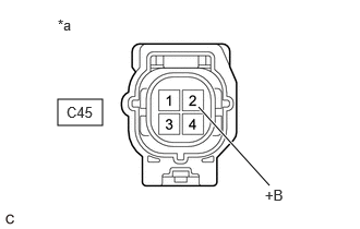
- CHECK TERMINAL VOLTAGE (POWER SOURCE OF AIR FUEL RATIO SENSOR (SENSOR 1))
*a Front view of wire harness connector
(to Air Fuel Ratio Sensor (Sensor 1))- Disconnect the air fuel ratio sensor (sensor 1) connector.
- Turn the ignition switch to ON.
- Measure the voltage according to the value(s) in the table below.
Standard Voltage
Tester Connection Condition Specified Condition C45-2 (+B) - Body ground Ignition switch ON 11 to 14 V Result
Proceed to OK NG
Result:
NG
See step 34
Result:
OK
See step 26
- CHECK HARNESS AND CONNECTOR (AIR FUEL RATIO SENSOR (SENSOR 1) - ECM)
- Disconnect the air fuel ratio sensor (sensor 1) connector.
- Disconnect the ECM connector.
- Measure the resistance according to the value(s) in the table below.
Standard Resistance
Tester Connection Condition Specified Condition C45-1 (HA1A) - C55-9 (HA1A) Always Below 1 Ω C45-3 (A1A+) - C55-95 (A1A+) Always Below 1 Ω C45-4 (A1A-) - C55-94 (A1A-) Always Below 1 Ω C45-1 (HA1A) or C55-9 (HA1A) - Body ground and other terminals Always 10 kΩ or higher C45-3 (A1A+) or C55-95 (A1A+) - Body ground and other terminals Always 10 kΩ or higher C45-4 (A1A-) or C55-94 (A1A-) - Body ground and other terminals Always 10 kΩ or higher Result
Proceed to OK NG
Result:
NG
REPAIR OR REPLACE HARNESS OR CONNECTOR
Result:
OK
See step 27
- REPLACE AIR FUEL RATIO SENSOR (SENSOR 1)
Refer to REMOVAL [12/2019 - ]
HINT:
Perform "Inspection After Repair" after replacing the air fuel ratio sensor (sensor 1).
Refer to INITIALIZATION [10/2021 - ]
Result
Proceed to NEXT Result:
NEXT
See step 28
- CLEAR DTC
- Clear the DTCs.
Powertrain > Engine > Clear DTCs
- Turn the ignition switch off and wait for at least 30 seconds.
Result
Proceed to NEXT
Result:
NEXT
See step 29
- Clear the DTCs.
- CONFIRM WHETHER MALFUNCTION HAS BEEN SUCCESSFULLY REPAIRED
- Drive the vehicle in accordance with the driving pattern described in Confirmation Driving Pattern.
- Read the DTCs.
Powertrain > Engine > Trouble Codes
Result
Result Proceed to DTCs are not output A DTC P0171-00, P0172-00, P1170-00 and/or P117B-00 is output B
Result:
A
END
Result:
B
See step 30
- READ VALUE USING GTS (MASS AIR FLOW SENSOR)
- Put the engine in Inspection Mode (Maintenance Mode).
Powertrain > Hybrid Control > Utility
Tester Display Inspection Mode - Start the engine and warm it up until the engine coolant temperature is 75°C (167°F) or higher with all the accessories switched off.
Powertrain > Engine > Data List
Tester Display Coolant Temperature - Read Mass Air Flow Sensor while maintaining an engine speed of 2500 rpm.
Powertrain > Engine > Data List
Tester Display Engine Speed Mass Air Flow Sensor HINT:
During charge control, the engine speed is set at idle. Therefore, the engine speed will not increase when the accelerator pedal is depressed. In this case, read the Data List after charge control has completed.
Standard
GTS Display Condition Specified Condition Mass Air Flow Sensor - Engine warmed up
- Shift position: P
- A/C: Off
- Engine Speed: 2500 rpm
Between 6.2 and 18.6 gm/sec Result
Proceed to NEXT
Result:
NEXT
See step 31
- Put the engine in Inspection Mode (Maintenance Mode).
- CHECK HARNESS AND CONNECTOR (MASS AIR FLOW METER SUB-ASSEMBLY CONNECTOR CONNECTION)
- Check the connection and terminal contact pressure of connectors and wire harnesses between the mass air flow meter sub-assembly and ECM.
Refer to ELECTRONIC CIRCUIT INSPECTION PROCEDURE [12/2019 - ]
HINT:
Repair any problems.
Result
Proceed to NEXT
Result:
NEXT
See step 32
- Check the connection and terminal contact pressure of connectors and wire harnesses between the mass air flow meter sub-assembly and ECM.
- CLEAR DTC
- Clear the DTCs.
Powertrain > Engine > Clear DTCs
- Turn the ignition switch off and wait for at least 30 seconds.
Result
Proceed to NEXT
Result:
NEXT
See step 33
- Clear the DTCs.
- CHECK WHETHER DTC OUTPUT RECURS (DTC P0171-00, P0172-00, P1170-00 OR P117B-00)
- Drive the vehicle in accordance with the driving pattern described in Confirmation Driving Pattern.
- Read the DTCs.
Powertrain > Engine > Trouble Codes
Result
Result Proceed to DTCs are not output A DTC P0171-00, P0172-00, P1170-00 and/or P117B-00 is output B
Result:
A
END
Result:
B
See step 38
- INSPECT EFI-MAIN NO. 2 RELAY
Refer to PROCEDURE - Step 2
Result
Proceed to OK NG Result:
NG
REPLACE EFI-MAIN NO. 2 RELAY
Result:
OK
See step 35
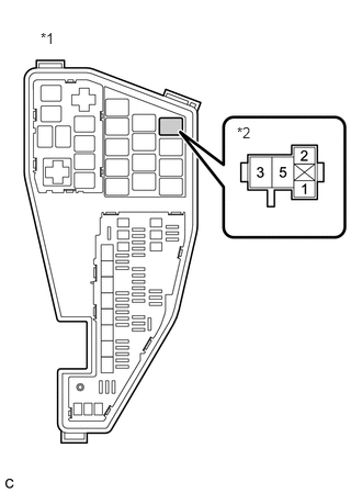
- CHECK TERMINAL VOLTAGE (POWER SOURCE OF EFI-MAIN NO. 2 RELAY)
*1 No. 1 Engine Room Relay Block and No. 1 Junction Block Assembly *2 EFI-MAIN NO. 2 Relay - Remove the EFI-MAIN NO. 2 relay from the No. 1 engine room relay block and No. 1 junction block assembly.
- Measure the voltage according to the value(s) in the table below.
Standard Voltage
Tester Connection Condition Specified Condition 3 (EFI-MAIN NO. 2 relay) - Body ground Always 11 to 14 V Result
Proceed to OK NG
Result:
NG
REPAIR OR REPLACE HARNESS OR CONNECTOR (AUXILIARY BATTERY - EFI-MAIN NO. 2 RELAY)
Result:
OK
See step 36
- CHECK HARNESS AND CONNECTOR (EFI-MAIN NO. 2 RELAY - BODY GROUND)
- Remove the EFI-MAIN NO. 2 relay from the No. 1 engine room relay block and No. 1 junction block assembly.
- Measure the resistance according to the value(s) in the table below.
Standard Resistance
Tester Connection Condition Specified Condition 1 (EFI-MAIN NO. 2 relay) - Body ground Always Below 1 Ω Result
Proceed to OK NG
Result:
NG
REPAIR OR REPLACE HARNESS OR CONNECTOR
Result:
OK
See step 37
- CHECK HARNESS AND CONNECTOR (EFI-MAIN NO. 2 RELAY - AIR FUEL RATIO SENSOR (SENSOR 1))
- Remove the EFI-MAIN NO. 2 relay from the No. 1 engine room relay block and No. 1 junction block assembly.
- Disconnect the air fuel ratio sensor (sensor 1) connector.
- Measure the resistance according to the value(s) in the table below.
Standard Resistance
Tester Connection Condition Specified Condition 5 (EFI-MAIN NO. 2 relay) - C45-2 (+B) Always Below 1 Ω 5 (EFI-MAIN NO. 2 relay) or C45-2 (+B) - Body ground and other terminals Always 10 kΩ or higher Result
Proceed to OK NG
Result:
OK
REPAIR OR REPLACE HARNESS OR CONNECTOR (EFI-MAIN NO. 1 RELAY - EFI-MAIN NO. 2 RELAY)
Result:
NG
REPAIR OR REPLACE HARNESS OR CONNECTOR
- CHECK HARNESS AND CONNECTOR (MASS AIR FLOW METER SUB-ASSEMBLY - ECM)
- Disconnect the mass air flow meter sub-assembly connector.
- Disconnect the ECM connector.
- Measure the resistance according to the value(s) in the table below.
Standard Resistance
Tester Connection Condition Specified Condition C30-3 (VCC) - C55-78 (VCVG) Always Below 1 Ω C30-1 (FG) - C55-101 (VG) Always Below 1 Ω C30-2 (E2G) - C55-79 (E2G) Always Below 1 Ω C30-3 (VCC) or C55-78 (VCVG) - Body ground and other terminals Always 10 kΩ or higher C30-1 (FG) or C55-101 (VG) - Body ground and other terminals Always 10 kΩ or higher C30-2 (E2G) or C55-79 (E2G) - Body ground and other terminals Always 10 kΩ or higher Result
Proceed to OK NG
Result:
NG
REPAIR OR REPLACE HARNESS OR CONNECTOR
Result:
OK
See step 39
- INSPECT MASS AIR FLOW METER SUB-ASSEMBLY
Refer to ON-VEHICLE INSPECTION [12/2019 - ]
Result
Proceed to NEXT Result:
NEXT
See step 40
- CLEAR DTC
- Clear the DTCs.
Powertrain > Engine > Clear DTCs
- Turn the ignition switch off and wait for at least 30 seconds.
Result
Proceed to NEXT
Result:
NEXT
See step 41
- Clear the DTCs.
- CONFIRM WHETHER MALFUNCTION HAS BEEN SUCCESSFULLY REPAIRED
- Drive the vehicle in accordance with the driving pattern described in Confirmation Driving Pattern.
- Read the DTCs.
Powertrain > Engine > Trouble Codes
Result
Result Proceed to DTCs are not output A DTC P0171-00, P0172-00, P1170-00 and/or P117B-00 is output B
Result:
A
END
Result:
B
REPLACE ECM
Refer to REMOVAL [10/2022 - 11/2023]