Installation [10/2022 - ]: Procedure
- INSTALL FRONT SHOULDER BELT ANCHOR ADJUSTER ASSEMBLY
HINT:
Perform this procedure only when replacement of the front shoulder belt anchor adjuster assembly is necessary.
- INSPECT FRONT SEAT OUTER BELT ASSEMBLY
See step 1
- INSTALL FRONT SEAT OUTER BELT ASSEMBLY
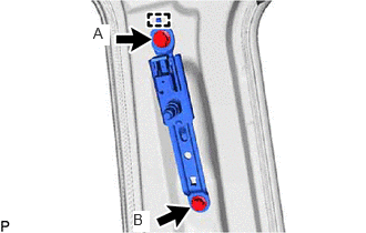
- Engage the 2 guides.
- Fully tighten the bolt.
Bolt (A)
Torque: 12.5 N*m (127 kgf*cm, 9 ft.*lbf)
- for LH Side:
- for RH Side:
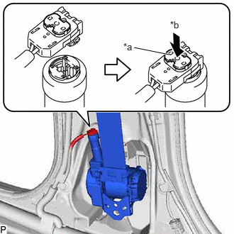
- Connect the selectable force limiter connector and lock the locking button as shown in the illustration.NOTE:
Securely lock the locking button.
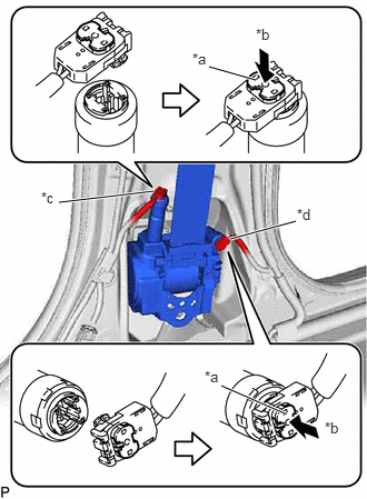
*a Locking Button *b Lock *c Pretensioner Connector *d Selectable Force Limiter Connector - Connect the pretensioner connector and lock the locking button as shown in the illustration.NOTE:
Securely lock the locking button.
- Connect the selectable force limiter connector and lock the locking button as shown in the illustration.
- Check that the ELR locks.NOTE:
The check should be performed with the front seat outer belt assembly installed.
- With the belt assembly installed, check that the belt locks when it is pulled out quickly.
- Connect the shoulder anchor of the front seat outer belt assembly with the nut.
Torque: 42 N*m (428 kgf*cm, 31 ft.*lbf)
- INSTALL CENTER PILLAR GARNISH ASSEMBLY
Refer to PROCEDURE - Step 40
- INSTALL LOWER CENTER PILLAR GARNISH
Refer to PROCEDURE - Step 41
- CONNECT FRONT SEAT OUTER BELT ASSEMBLY
- Connect the floor anchor of the front seat outer belt assembly with the bolt.
Torque: 42 N*m (428 kgf*cm, 31 ft.*lbf)
- Connect the floor anchor of the front seat outer belt assembly with the bolt.
- INSTALL LAP BELT OUTER ANCHOR COVER
- Engage the 3 claws to install the lap belt outer anchor cover.
- CONNECT REAR DOOR OPENING TRIM WEATHERSTRIP
Refer to PROCEDURE - Step 1
- INSTALL REAR DOOR SCUFF PLATE
Refer to PROCEDURE - Step 45
- INSTALL REAR OUTER SEAT TRACK BRACKET COVER
Refer to PROCEDURE - Step 46
- CONNECT FRONT DOOR OPENING TRIM WEATHERSTRIP
Refer to PROCEDURE - Step 1
- INSTALL FRONT DOOR SCUFF PLATE
Refer to PROCEDURE - Step 50
- CONNECT CABLE TO NEGATIVE BATTERY TERMINAL
- INSTALL BATTERY SERVICE HOLE COVER (for HV Model)
Refer to PROCEDURE - Step 3 [12/2019 - 11/2023] , or refer to PROCEDURE - Step 3 [11/2023 - ]
- INSPECT SRS WARNING LIGHT
Refer to SYSTEM DIAGRAM [10/2021 - 11/2023] , or refer to SYSTEM DIAGRAM [11/2023 - ]