Installation [12/2019 - ]: Procedure
- INSTALL FRONT DRIVE SHAFT HOLE SNAP RING
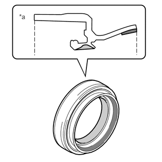
- Install a new front drive shaft hole snap ring.NOTE:
Face the end gap of the front drive shaft hole snap ring downward.
- Install a new front drive shaft hole snap ring.
- INSTALL FRONT DRIVE SHAFT ASSEMBLY LH
- Coat the front drive shaft hole snap ring of the front drive inboard joint assembly with MP grease.
- Coat the splines of the front drive inboard joint assembly with Toyota genuine ATF WS.
- Coat the lip of the front drive shaft oil seal LH with MP grease and Toyota genuine oil seal side lip grease as shown in the illustration.
*a Cross Section of Front Drive Shaft Oil Seal LH 
MP Grease 
Toyota Genuine Oil Seal Side Lip Grease HINT:
Apply a light coat of MP grease and Toyota genuine oil seal side lip grease to the entire circumference of the front drive shaft oil seal LH.
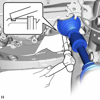
- Align the inboard joint splines, and using a brass bar and a hammer, install the front drive shaft assembly LH.NOTE:
- Face the end gap of the front drive shaft hole snap ring downward.
- Do not damage the front drive shaft oil seal LH.
- Do not damage the front axle inboard joint boot.
- Make sure to center the front drive shaft assembly LH during installation to prevent damage to the front drive shaft hole snap ring.
HINT:
Confirm whether the drive shaft is securely driven in by checking the reaction force and sound.
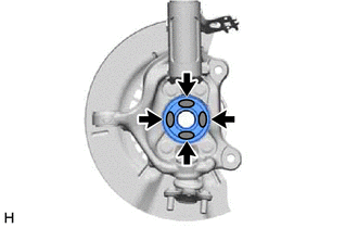
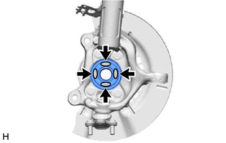
- Apply 0.1 to 0.3 g (0.00353 to 0.0105 oz) of Toyota Body Grease W to each of the 4 areas shown in the illustration.

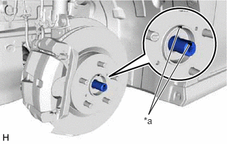
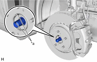
Toyota Body Grease W - Align the matchmarks and install the front drive shaft assembly LH to the front axle assembly.
*a Matchmark NOTE:- Do not damage the front disc brake dust cover.
- Do not damage the front axle outboard joint boot.
- Check that there is no foreign matter on the deflector or contact surfaces.
- Do not push the front axle assembly towards the outside of the vehicle any further than necessary.
- Do not damage the deflector.
- INSTALL FRONT DRIVE SHAFT ASSEMBLY RH
- Coat the splines of the front drive inboard joint assembly with Toyota genuine ATF WS.
- Coat the lip of the front drive shaft oil seal RH with MP grease and Toyota genuine oil seal side lip grease as shown in the illustration.
HINT:
Apply a light coat of MP grease and Toyota genuine oil seal side lip grease to the entire circumference of the front drive shaft oil seal RH.
*a Cross Section of Front Drive Shaft Oil Seal RH MP Grease Toyota Genuine Oil Seal Side Lip Grease - Align the inboard joint splines, and securely insert the front drive shaft assembly RH.NOTE:
- Do not damage the front drive shaft oil seal RH.
- Do not damage the front axle inboard joint boot.
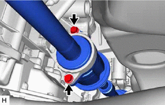
- Install the front drive shaft assembly RH with the 2 bolts.
Torque: 50.5 N.m (515 kgf/cm, 37 ft.lbf)
- Apply 0.1 to 0.3 g (0.00353 to 0.0105 oz) of Toyota Body Grease W to each of the 4 areas shown in the illustration.
Toyota Body Grease W - Align the matchmarks and install the front drive shaft assembly RH to the front axle assembly.
*a Matchmark NOTE:- Do not damage the front disc brake dust cover.
- Do not damage the front axle outboard joint boot.
- Check that there is no foreign matter on the deflector or contact surfaces.
- Do not push the front axle assembly towards the outside of the vehicle any further than necessary.
- Do not damage the deflector.
- CONNECT FRONT LOWER NO. 1 SUSPENSION ARM SUB-ASSEMBLY
Refer to PROCEDURE - Step 4
- INSTALL FRONT STABILIZER LINK ASSEMBLY
Refer to PROCEDURE - Step 13
- CONNECT TIE ROD ASSEMBLY
Refer to PROCEDURE - Step 10 [12/2019 - 10/2022] , or refer to PROCEDURE - Step 9 [10/2022 - 11/2023] , or refer to PROCEDURE - Step 9 [11/2023 - ]
- INSTALL FRONT SPEED SENSOR
Refer to PROCEDURE - Step 15
- INSTALL FRONT AXLE SHAFT NUT
- Clean the threaded parts on the front drive shaft assembly and a new front axle shaft nut using non-residue solvent.NOTE:
- Make sure to perform this work even when using a new front drive shaft assembly.
- Keep the threaded parts free of oil and foreign matter.
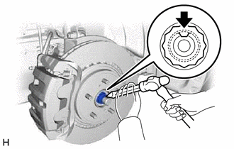
- Using a 30 mm deep socket wrench, install the front axle shaft nut.
Torque: 294 N.m (2998 kgf/cm, 217 ft.lbf)
HINT:
Depress the brake pedal to prevent the drive shaft from rotating.
- Using a chisel and hammer, stake the front axle shaft nut.
- Clean the threaded parts on the front drive shaft assembly and a new front axle shaft nut using non-residue solvent.
- ADD HYBRID TRANSAXLE FLUID
Refer to PROCEDURE - Step 6 [12/2019 - 11/2023] , or refer to PROCEDURE - Step 6 [11/2023 - ]
- INSPECT HYBRID TRANSAXLE FLUID
Refer to PROCEDURE - Step 5 [12/2019 - 11/2023] , or refer to PROCEDURE - Step 5 [11/2023 - ]
- INSPECT FOR HYBRID TRANSAXLE FLUID LEAK
- INSTALL FRONT WHEELS
Refer to INSTALLATION [12/2019 - 10/2022] , or refer to INSTALLATION [10/2022 - ]
- INSPECT AND ADJUST FRONT WHEEL ALIGNMENT
Refer to ADJUSTMENT [12/2019 - 09/2020] , or refer to ADJUSTMENT [09/2020 - 10/2022] , or refer to ADJUSTMENT [10/2022 - 11/2023] , or refer to ADJUSTMENT [11/2023 - 11/2024] , or refer to ADJUSTMENT [11/2024 - ]
- INSTALL FRONT FENDER APRON SEAL LH
Refer to PROCEDURE - Step 60 [12/2019 - 10/2022] , or refer to PROCEDURE - Step 60 [10/2022 - 11/2023] , or refer to PROCEDURE - Step 58 [11/2023 - ]
- INSTALL FRONT FENDER APRON SEAL RH
Refer to PROCEDURE - Step 61 [12/2019 - 10/2022] , or refer to PROCEDURE - Step 61 [10/2022 - 11/2023] , or refer to PROCEDURE - Step 59 [11/2023 - ]
- INSTALL NO. 2 ENGINE UNDER COVER ASSEMBLY
Refer to PROCEDURE - Step 62 [12/2019 - 10/2022] , or refer to PROCEDURE - Step 62 [10/2022 - 11/2023] , or refer to PROCEDURE - Step 60 [11/2023 - ]
- INSTALL NO. 1 ENGINE UNDER COVER
Refer to PROCEDURE - Step 63 [12/2019 - 10/2022] , or refer to PROCEDURE - Step 63 [10/2022 - 11/2023] , or refer to PROCEDURE - Step 61 [11/2023 - ]
- INSTALL FRONT WHEEL OPENING EXTENSION PAD LH
Refer to PROCEDURE - Step 64 [12/2019 - 10/2022] , or refer to PROCEDURE - Step 64 [10/2022 - 11/2023] , or refer to PROCEDURE - Step 62 [11/2023 - ]
- INSTALL FRONT WHEEL OPENING EXTENSION PAD RH
Refer to PROCEDURE - Step 65 [12/2019 - 10/2022] , or refer to PROCEDURE - Step 65 [10/2022 - 11/2023] , or refer to PROCEDURE - Step 63 [11/2023 - ]
- CHECK FOR SPEED SENSOR SIGNAL
Refer to TEST MODE PROCEDURE [12/2019 - 11/2023] , or refer to TEST MODE PROCEDURE [11/2023 - ]