Installation [12/2019 - 09/2020]: Procedure
- INSTALL COOLER CONDENSER ASSEMBLY (for Gasoline Model)
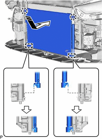
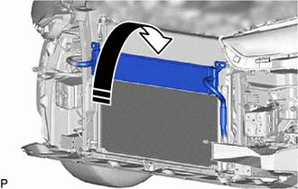
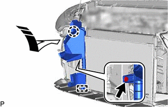
- Engage the 2 guides and 2 claws to install the cooler condenser assembly as shown in the illustration.

Install in this Direction NOTE:Do not damage the cooler condenser assembly or radiator assembly when installing the cooler condenser assembly.
HINT:
If a new cooler condenser assembly is installed, add compressor oil to the cooler condenser assembly as follows.
Capacity
Add 40 cc (1.35 fl. oz)
Compressor Oil
ND-OIL 12 or equivalent
- Engage the 2 guides and 2 claws to install the cooler condenser assembly as shown in the illustration.
- INSTALL COOLER CONDENSER ASSEMBLY (for HV Model)
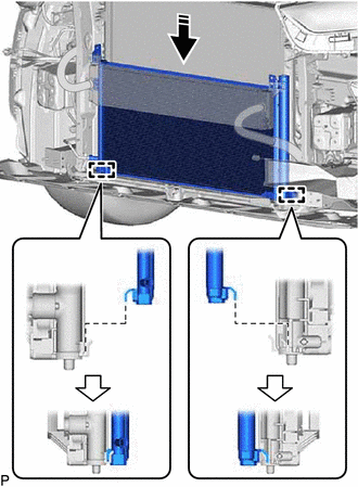
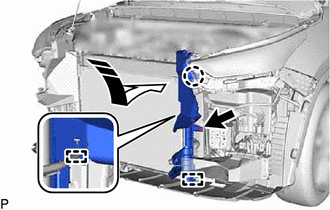
- Engage the 2 guides to install the cooler condenser assembly as shown in the illustration.
Install in this Direction NOTE:Do not damage the cooler condenser assembly or radiator assembly when installing the cooler condenser assembly.
HINT:
If a new cooler condenser assembly is installed, add compressor oil to the cooler condenser assembly as follows.
Capacity
Add 40 cc (1.35 fl. oz)
Compressor Oil
ND-OIL 11 or equivalent
- Engage the 2 guides to install the cooler condenser assembly as shown in the illustration.
- CONNECT AIR CONDITIONING TUBE ASSEMBLY (for Gasoline Model)
- Remove the vinyl tape from the cooler condenser assembly and air conditioning tube assembly.
- Install a new piping clamp to the air conditioning tube assembly.
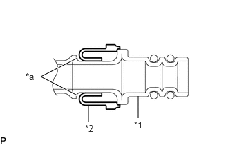
*1 Air Conditioning Tube Assembly *2 Piping Clamp *a Groove NOTE:- Securely engage the piping clamp to the groove of the air conditioning tube assembly.
- Do not open the piping clamp more than the diameter of the air conditioning tube assembly when installing it.
- Do not install the piping clamp with the large diameter section facing the wrong direction.
- Sufficiently apply compressor oil to 2 new O-rings and the fitting surfaces of the air conditioning tube assembly.
Compressor Oil
ND-OIL 12 or equivalent
- Install the 2 O-rings to the air conditioning tube assembly.NOTE:
Keep the O-rings and O-ring fitting surfaces free from foreign matter.
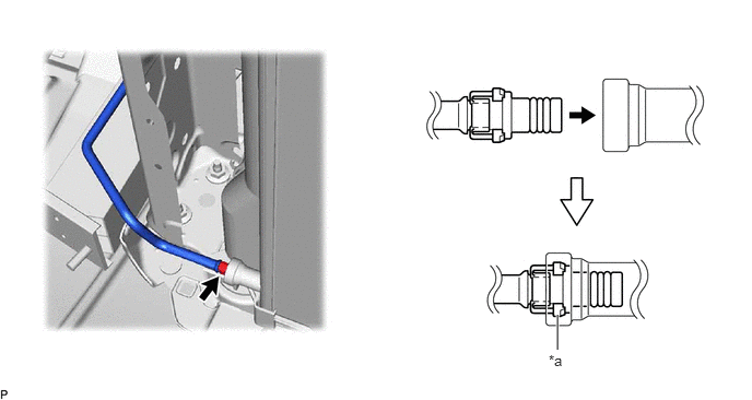
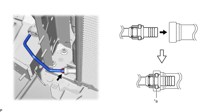
- Connect the air conditioning tube assembly to the cooler condenser assembly.
*a Large Diameter Section of Piping Clamp - - NOTE:Connect the parts by holding the pipe, not the piping clamp.
- Securely insert the piping clamp to the point where the large diameter section of the piping clamp is covered by the cooler condenser assembly.
HINT:
- When inserting, make sure that a click sound is heard.
- Check that the cooler condenser assembly is securely connected by pulling it.
- CONNECT COOLER REFRIGERANT LIQUID PIPE A (for HV Model)
- Remove the vinyl tape from the cooler condenser assembly and cooler refrigerant liquid pipe A.
- Install a new piping clamp to the cooler refrigerant liquid pipe A.
*1 Cooler Refrigerant Liquid Pipe A *2 Piping Clamp *a Groove NOTE:- Securely engage the piping clamp to the groove of the cooler refrigerant liquid pipe A.
- Do not open the piping clamp more than the diameter of the cooler refrigerant liquid pipe A when installing it.
- Do not install the piping clamp with the large diameter section facing the wrong direction.
- Sufficiently apply compressor oil to 2 new O-rings and the fitting surfaces of the cooler refrigerant liquid pipe A.
Compressor Oil
ND-OIL 11 or equivalent
- Install the 2 O-rings to the cooler refrigerant liquid pipe A.NOTE:
Keep the O-rings and O-ring fitting surfaces free from foreign matter.
- Connect the cooler refrigerant liquid pipe A to the cooler condenser assembly.
*a Large Diameter Section of Piping Clamp - - NOTE:Connect the parts by holding the pipe, not the piping clamp.
- Securely insert the piping clamp to the point where the large diameter section of the piping clamp is covered by the cooler condenser assembly.
HINT:
- When inserting, make sure that a click sound is heard.
- Check that the cooler refrigerant liquid pipe A is securely connected by pulling it.
- CONNECT DISCHARGE HOSE SUB-ASSEMBLY (for Gasoline Model)
- Remove the vinyl tape from the discharge hose sub-assembly and cooler condenser assembly.
- Sufficiently apply compressor oil to a new O-ring and the fitting surface of the discharge hose sub-assembly.
Compressor Oil
ND-OIL 12 or equivalent
- Install the O-ring to the discharge hose sub-assembly.NOTE:
Keep the O-rings and O-ring fitting surfaces free from foreign matter.
- Connect the discharge hose sub-assembly to the cooler condenser assembly with the bolt.
Torque: 5.4 N.m (55 kgf/cm, 48 in.lbf)
- CONNECT DISCHARGE HOSE SUB-ASSEMBLY (for HV Model)
- Remove the vinyl tape from the discharge hose sub-assembly and cooler condenser assembly.
- Sufficiently apply compressor oil to a new O-ring and the fitting surface of the discharge hose sub-assembly.
Compressor Oil
ND-OIL 11 or equivalent
- Install the O-ring to the discharge hose sub-assembly.NOTE:
Keep the O-rings and O-ring fitting surfaces free from foreign matter.
- Connect the discharge hose sub-assembly to the cooler condenser assembly with the bolt.
Torque: 5.4 N.m (55 kgf/cm, 48 in.lbf)
- CONNECT RADIATOR ASSEMBLY (for HV Model)
- for Inverter Coolant:
- Install the radiator assembly to its original position as shown in the illustration.
Install in this Direction NOTE:Do not apply excessive force to the No. 3 inverter cooling hose and No. 4 inverter cooling hose.
- Engage the 2 claws.NOTE:
Be careful not to damage the radiator assembly (for inverter coolant) or radiator assembly.
- Install the 4 bolts.
Torque: 9.0 N.m (92 kgf/cm, 80 in.lbf)
- Install the radiator assembly to its original position as shown in the illustration.
- for Inverter Coolant:
- INSTALL NO. 1 RADIATOR AIR GUIDE RH
- INSTALL NO. 1 RADIATOR AIR GUIDE LH
- INSTALL THERMISTOR ASSEMBLY (w/o Grille Shutter)
See step 1
- INSTALL UPPER RADIATOR SUPPORT SUB-ASSEMBLY (for 2GR-FKS)
Refer to PROCEDURE - Step 9
- INSTALL UPPER RADIATOR SUPPORT SUB-ASSEMBLY (for A25A-FXS)
Refer to PROCEDURE - Step 11
- INSTALL INLET AIR CLEANER ASSEMBLY (for 2GR-FKS)
Refer to PROCEDURE - Step 51
- INSTALL INLET AIR CLEANER ASSEMBLY (for A25A-FXS)
Refer to PROCEDURE - Step 20
- INSTALL HOOD LOCK ASSEMBLY
Refer to PROCEDURE - Step 6
- INSTALL FRONT BUMPER REINFORCEMENT SUB-ASSEMBLY
Refer to PROCEDURE - Step 4
- INSTALL FRONT BUMPER ENERGY ABSORBER
Refer to PROCEDURE - Step 6
- INSTALL RADIATOR SHUTTER SUB-ASSEMBLY (w/ Grille Shutter)
Refer to INSTALLATION [12/2019 - 09/2020]
- INSTALL FRONT BUMPER ASSEMBLY (w/o Grille Shutter)
Refer to INSTALLATION [12/2019 - 09/2020]
- CHARGE AIR CONDITIONING SYSTEM WITH REFRIGERANT
Refer to PROCEDURE - Step 2
- WARM UP ENGINE (for Gasoline Model)
Refer to PROCEDURE - Step 3
- WARM UP COMPRESSOR (for HV Model)
Refer to PROCEDURE - Step 4
- INSPECT FOR REFRIGERANT LEAK
Refer to PROCEDURE - Step 5
- ADJUST HOOD SUB-ASSEMBLY
Refer to ADJUSTMENT [12/2019 - 09/2020]