Installation [12/2019 - ]: Procedure
- INSTALL HOLE PLUG
- INSTALL BOLT (for 2WD)
- INSTALL REAR SUSPENSION MEMBER FRONT BODY MOUNTING CUSHION (for LH Side)
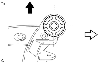
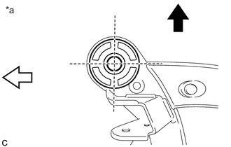
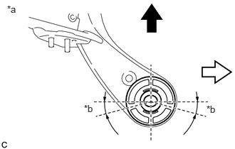
- Confirm the installation direction and temporarily install a new rear suspension member front body mounting cushion.NOTE:
- Position the rear suspension member front body mounting cushion in the correct direction.
- Do not apply lubricant to the outer sleeve of the rear suspension member front body mounting cushion.
*a View from Underneath 
Front of the Vehicle 
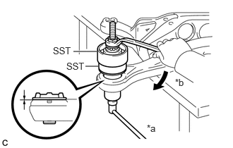
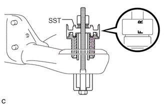
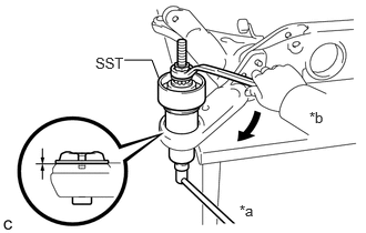
Outside of the Vehicle - Install SST as shown in the illustration.
- SST: 09527-17011
- SST: 09830-10010
- 09830-01010
- 09830-01020
- 09830-01030
- 09830-01060
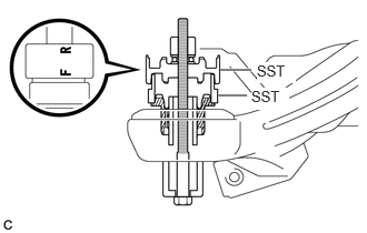
NOTE:Apply molybdenum grease to the threads and tip of the SST center bolt before use.
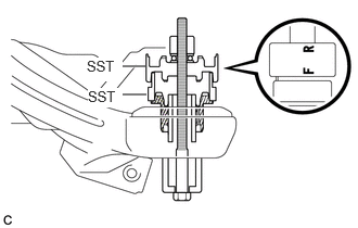
HINT:
Use SST with the "F" mark facing the rear suspension member front body mounting cushion.
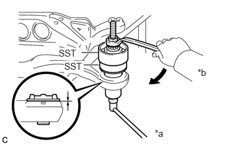
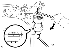
- Using SST, install the rear suspension member front body mounting cushion until there is no clearance between the rear suspension member sub-assembly and rear suspension member front body mounting cushion.
- SST: 09527-17011
- SST: 09830-10010
- 09830-01010
- 09830-01020
- 09830-01030
- 09830-01060
NOTE:If the rear suspension member sub-assembly is scratched, apply paint to the scratched areas of the rear suspension member sub-assembly.
*a Hold *b Turn - Remove SST from the rear suspension member sub-assembly.
- Confirm the installation direction and temporarily install a new rear suspension member front body mounting cushion.
- INSTALL REAR SUSPENSION MEMBER FRONT BODY MOUNTING CUSHION (for RH Side)
- Confirm the installation direction and temporarily install a new rear suspension member front body mounting cushion.NOTE:
- Position the rear suspension member front body mounting cushion in the correct direction.
- Do not apply lubricant to the outer sleeve of the rear suspension member front body mounting cushion.
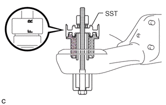
*a View from Underneath Front of the Vehicle Outside of the Vehicle - Install SST as shown in the illustration.
- SST: 09527-17011
- SST: 09830-10010
- 09830-01010
- 09830-01020
- 09830-01030
- 09830-01060
NOTE:Apply molybdenum grease to the threads and tip of the SST center bolt before use.
HINT:
Use SST with the "F" mark facing the rear suspension member front body mounting cushion.
- Using SST, install the rear suspension member front body mounting cushion until there is no clearance between the rear suspension member sub-assembly and rear suspension member front body mounting cushion.
- SST: 09527-17011
- SST: 09830-10010
- 09830-01010
- 09830-01020
- 09830-01030
- 09830-01060
NOTE:If the rear suspension member sub-assembly is scratched, apply paint to the scratched areas of the rear suspension member sub-assembly.
*a Hold *b Turn - Remove SST from the rear suspension member sub-assembly.
- Confirm the installation direction and temporarily install a new rear suspension member front body mounting cushion.
- INSTALL REAR SUSPENSION MEMBER REAR BODY MOUNT CUSHION LH
- Confirm the installation direction and temporarily install a new rear suspension member rear body mount cushion LH.NOTE:
- Position the rear suspension member rear body mount cushion LH in the correct direction.
- Do not apply lubricant to the outer sleeve of the rear suspension member rear body mount cushion LH.
*a View from Underneath *b 15° Front of the Vehicle Outside of the Vehicle - Install SST as shown in the illustration.
- SST: 09830-10010
- 09830-01010
- 09830-01020
- 09830-01030
- 09830-01060
NOTE:Apply molybdenum grease to the threads and tip of the SST center bolt before use.
HINT:
Use SST with the "F" mark facing the rear suspension member rear body mount cushion LH.
- SST: 09830-10010
- Using SST, install the rear suspension member rear body mount cushion LH until there is no clearance between the rear suspension member sub-assembly and rear suspension member rear body mount cushion LH.
- SST: 09830-10010
- 09830-01010
- 09830-01020
- 09830-01030
- 09830-01060
NOTE:If the rear suspension member sub-assembly is scratched, apply paint to the scratched areas of the rear suspension member sub-assembly.
*a Hold *b Turn - SST: 09830-10010
- Remove SST from the rear suspension member sub-assembly.
- Confirm the installation direction and temporarily install a new rear suspension member rear body mount cushion LH.
- INSTALL REAR SUSPENSION MEMBER REAR BODY MOUNT CUSHION RH
- Confirm the installation direction and temporarily install a new rear suspension member rear body mount cushion RH.NOTE:
- Position the rear suspension member rear body mount cushion RH in the correct direction.
- Do not apply lubricant to the outer sleeve of the rear suspension member rear body mount cushion RH.
*a View from Underneath Front of the Vehicle Outside of the Vehicle - Install SST as shown in the illustration.
- SST: 09830-10010
- 09830-01010
- 09830-01020
- 09830-01030
- 09830-01060
NOTE:Apply molybdenum grease to the threads and tip of the SST center bolt before use.
HINT:
Use SST with the "F" mark facing the rear suspension member rear body mount cushion RH.
- SST: 09830-10010
- Using SST, install the rear suspension member rear body mount cushion RH until there is no clearance between the rear suspension member sub-assembly and rear suspension member rear body mount cushion RH.
- SST: 09830-10010
- 09830-01010
- 09830-01020
- 09830-01030
- 09830-01060
NOTE:If the rear suspension member sub-assembly is scratched, apply paint to the scratched areas of the rear suspension member sub-assembly.
*a Hold *b Turn - SST: 09830-10010
- Remove SST from the rear suspension member sub-assembly.
- Confirm the installation direction and temporarily install a new rear suspension member rear body mount cushion RH.
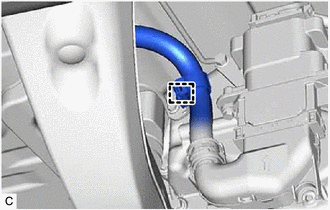
- INSTALL DIFFERENTIAL MOUNT CUSHION (for AWD)
- Temporarily install a new differential mount cushion to the rear suspension member sub-assembly from the rear of the vehicle as shown in the illustration.
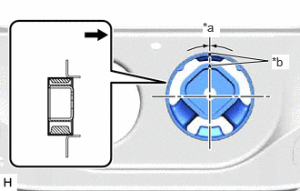
*a -3° to 3° *b Protrusion Front of the Vehicle NOTE:- Make sure that the differential mount cushion is aligned within 3° from the center.
- Install the differential mount cushion so that the protrusion is positioned as shown in the illustration.
- Be sure to install the differential mount cushion in the correct direction.
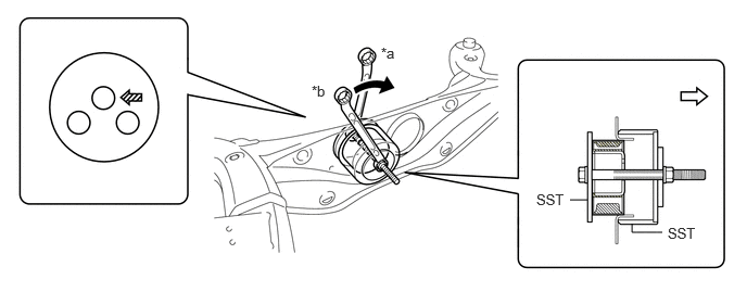
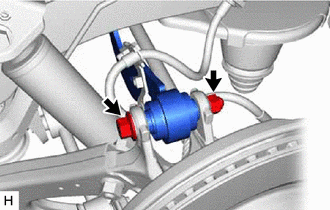
- Using SST, press the differential mount cushion into the rear suspension member sub-assembly. (Step *1)
- SST: 09570-24011
*a Hold *b Turn Front of Vehicle 
SST Bolt Position NOTE:- Apply molybdenum grease to the threads of the SST center bolt before use.
- Be sure to install the SST bolt straight.
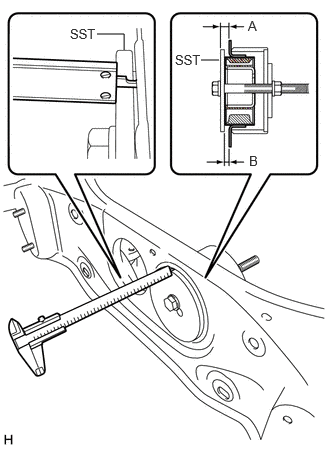
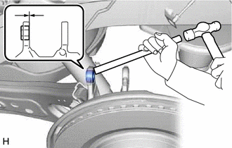
- Using a vernier caliper, measure the length indicated by (A) in the illustration. (Step *2)NOTE:
- Measure at several points to ensure that the differential mount cushion is pressed in evenly.
- Do not measure on a weld bead.
- Repeat the steps *1 and *2 to press the differential mount cushion into the rear suspension member sub-assembly until the length indicated by (A) in the illustration is within the specification.
Reference Length (A)
13.6 to 14.6 mm (0.535 to 0.575 in.)
HINT:
Reference length (A) = Standard length (B) + Thickness of SST
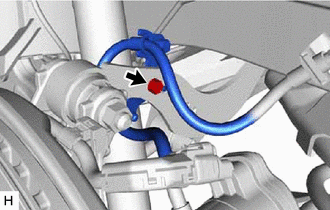
- Remove SST. Using a vernier caliper, measure the differential mount cushion protrusion length indicated by (B) in the illustration and ensure that the measured length is within the specification.
Standard Length (B)
7.6 to 8.6 mm (0.299 to 0.339 in.)
- Temporarily install a new differential mount cushion to the rear suspension member sub-assembly from the rear of the vehicle as shown in the illustration.
- INSTALL REAR UPPER CONTROL ARM ASSEMBLY LH
See step 1
- INSTALL REAR UPPER CONTROL ARM ASSEMBLY RH
HINT:
Perform the same procedure as for the LH side.
- INSTALL REAR SUSPENSION MEMBER UPPER STOPPER
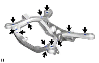
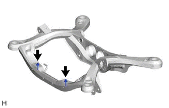
- Install the 2 rear suspension member upper stoppers to the rear suspension member sub-assembly.
- INSTALL REAR SUSPENSION MEMBER LOWER STOPPER RETAINER
- Install the 2 rear suspension member lower stopper retainers to the rear suspension member sub-assembly.
- INSTALL REAR TRACTION MOTOR WITH TRANSAXLE ASSEMBLY (for AWD)
Refer to PROCEDURE - Step 6
- INSTALL REAR SUSPENSION MEMBER SUB-ASSEMBLY
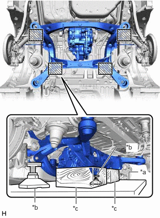
- Using an engine lifter, 2 attachments and 2 wooden blocks or equivalent tools, support the rear suspension member sub-assembly, and raise the rear suspension member sub-assembly until there is no clearance between the rear suspension member sub-assembly and vehicle body.
*a Engine Lifter *b Attachment *c Wooden Block 
Attachment and Wooden Block Placement Location WARNING:- The rear suspension member sub-assembly is a very heavy component. Make sure that it is supported securely.
- If the rear suspension member sub-assembly is not securely supported, it may drop, resulting in serious injury.
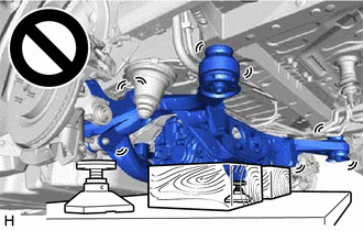
NOTE:- Use attachments and wooden blocks to keep the rear suspension member sub-assembly level.
- Keep supporting the rear suspension member sub-assembly until the installation has been completed.
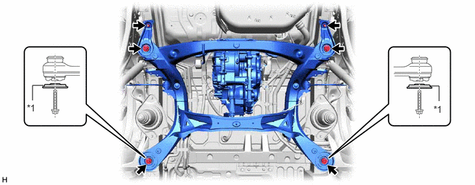
- Install the rear suspension member sub-assembly with the 2 rear lower suspension braces, rear lower suspension member stopper LH and rear lower suspension member stopper RH, with the 4 bolts and 2 nuts.
*1 Rear Lower Suspension Brace - - Bolt
Torque: 158 N.m (1611 kgf/cm, 117 ft.lbf)
Nut
Torque: 32 N.m (326 kgf/cm, 24 ft.lbf)
NOTE:Be sure to install the rear suspension member sub-assembly with the rear lower suspension braces facing in the correct direction as shown in the illustration.
- Using an engine lifter, 2 attachments and 2 wooden blocks or equivalent tools, support the rear suspension member sub-assembly, and raise the rear suspension member sub-assembly until there is no clearance between the rear suspension member sub-assembly and vehicle body.
- CONNECT FLOOR UNDER WIRE (for AWD) WARNING:
Be sure to wear insulated gloves.
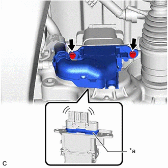
- Install the HV floor under wire to the rear traction motor with transaxle assembly with the 2 bolts.
Torque: 8.0 N.m (82 kgf/cm, 71 in.lbf)
NOTE:- Make sure that the connector is fully engaged.
- Do not damage the terminals, interlock connector or rear traction motor with transaxle assembly during installation.
- Do not touch the waterproof seal or terminals of the connector.
- Do not allow any foreign matter or water to enter the rear traction motor with transaxle assembly.
- Although the connector may feel loose, this is not due to a malfunction.
*a Waterproof Seal - Engage the clamp.
- Install the HV floor under wire to the rear traction motor with transaxle assembly with the 2 bolts.
- INSTALL FRAME WIRE (w/ Wire Harness)
- w/ Height Control Sensor:
- Engage the clamp.
- Install the frame wire to the rear suspension member sub-assembly with the nut.
Torque: 8.0 N.m (82 kgf/cm, 71 in.lbf)
- for AWD:
- Install the frame wire to the rear suspension member sub-assembly with the bolt and clamp.
Torque: 8.0 N.m (82 kgf/cm, 71 in.lbf)
- Install the frame wire to the rear traction motor with transaxle assembly with the 2 bolts.
Torque: 10 N.m (102 kgf/cm, 7 ft.lbf)
- Connect the 2 connectors.
- Install the frame wire to the rear suspension member sub-assembly with the bolt and clamp.
- for 2WD:
- Install the frame wire to the rear suspension member sub-assembly with the bolt.
Torque: 8.0 N.m (82 kgf/cm, 71 in.lbf)
- Install the frame wire to the rear suspension member sub-assembly with the bolt.
- w/ Height Control Sensor:
- INSTALL REAR DRIVE SHAFT LH SNAP RING (for AWD)
Refer to PROCEDURE - Step 1
- INSTALL REAR DRIVE SHAFT RH SNAP RING (for AWD)
HINT:
Perform the same procedure as for the LH side.
- INSTALL REAR DRIVE SHAFT ASSEMBLY LH (for AWD)
Refer to PROCEDURE - Step 2
- INSTALL REAR DRIVE SHAFT ASSEMBLY RH (for AWD)
HINT:
Perform the same procedure as for the LH side.
- TEMPORARILY INSTALL REAR UPPER CONTROL ARM ASSEMBLY LH
- Using a brass bar and a hammer, push out the bushing until it is positioned as shown in the illustration.
HINT:
Pushing out the bushing makes it easier to connect the rear upper control arm assembly LH.
- Temporarily install the rear axle carrier sub-assembly to the rear upper control arm assembly with the bolt and nut.NOTE:
- Insert the bolt with the threaded end facing the rear of the vehicle.
- Because the nut has its own stopper, do not turn the nut. Tighten the bolt with the nut secured.
- Using a brass bar and a hammer, push out the bushing until it is positioned as shown in the illustration.
- TEMPORARILY INSTALL REAR UPPER CONTROL ARM ASSEMBLY RH
HINT:
Perform the same procedure as for the LH side.
- TEMPORARILY INSTALL REAR NO. 1 SUSPENSION ARM ASSEMBLY LH
- TEMPORARILY INSTALL REAR NO. 1 SUSPENSION ARM ASSEMBLY RH
HINT:
Perform the same procedure as for the LH side.
- TEMPORARILY INSTALL REAR NO. 2 SUSPENSION ARM ASSEMBLY LH
- TEMPORARILY INSTALL REAR NO. 2 SUSPENSION ARM ASSEMBLY RH
HINT:
Perform the same procedure as for the LH side.
- INSTALL REAR LOWER COIL SPRING INSULATOR LH
- INSTALL REAR LOWER COIL SPRING INSULATOR RH
HINT:
Perform the same procedure as for the LH side.
- INSTALL REAR COIL SPRING LH
- INSTALL REAR COIL SPRING RH
HINT:
Perform the same procedure as for the LH side.
- INSTALL REAR LOWER STABILIZER BRACKET
See step 3
- INSTALL REAR STABILIZER BAR
See step 4
- TEMPORARILY INSTALL REAR STABILIZER LINK ASSEMBLY LH
See step 5
- TEMPORARILY INSTALL REAR STABILIZER LINK ASSEMBLY RH
HINT:
Perform the same procedure as for the LH side.
- INSTALL REAR SKID CONTROL SENSOR LH (for AWD)
Refer to PROCEDURE - Step 14
- INSTALL REAR SKID CONTROL SENSOR RH (for AWD)
HINT:
Perform the same procedure as for the LH side.
- CONNECT NO. 2 PARKING BRAKE WIRE ASSEMBLY (for AWD)
- Connect the No. 2 parking brake wire assembly connector to the rear skid control sensor.
- CONNECT NO. 1 PARKING BRAKE WIRE ASSEMBLY (for AWD)
HINT:
Perform the same procedure as for the LH side.
- INSTALL REAR AXLE SHAFT NUT LH (for AWD)
Refer to PROCEDURE - Step 11
- INSTALL REAR AXLE SHAFT NUT RH (for AWD)
HINT:
Perform the same procedure as for the LH side.
- INSTALL REAR HEIGHT CONTROL SENSOR SUB-ASSEMBLY LH (w/ Height Control Sensor)
Refer to INSTALLATION [12/2019 - ]
- CONNECT REAR FLEXIBLE HOSE LH
- CONNECT REAR FLEXIBLE HOSE RH
HINT:
Perform the same procedure as for the LH side.
- STABILIZE SUSPENSION
See step 3
- INSTALL REAR NO. 1 SUSPENSION ARM ASSEMBLY LH
- INSTALL REAR NO. 1 SUSPENSION ARM ASSEMBLY RH
HINT:
Perform the same procedure as for the LH side.
- INSTALL REAR NO. 2 SUSPENSION ARM ASSEMBLY LH
- INSTALL REAR NO. 2 SUSPENSION ARM ASSEMBLY RH
HINT:
Perform the same procedure as for the LH side.
- INSTALL REAR STABILIZER LINK ASSEMBLY LH
See step 8
- INSTALL REAR STABILIZER LINK ASSEMBLY RH
HINT:
Perform the same procedure as for the LH side.
- INSTALL REAR UPPER CONTROL ARM ASSEMBLY LH
- Install the rear upper control arm assembly to the rear axle carrier sub-assembly with the bolt.
Torque: 110 N.m (1122 kgf/cm, 81 ft.lbf)
NOTE:Because the nut has its own stopper, do not turn the nut. Tighten the bolt with the nut secured.
- Install the rear upper control arm assembly to the rear axle carrier sub-assembly with the bolt.
- INSTALL REAR UPPER CONTROL ARM ASSEMBLY RH
HINT:
Perform the same procedure as for the LH side.
- INSTALL REAR SUSPENSION ARM COVER LH
- INSTALL REAR SUSPENSION ARM COVER RH
HINT:
Perform the same procedure as for the LH side.
- INSTALL TAIL EXHAUST PIPE ASSEMBLY
Refer to INSTALLATION [12/2019 - 10/2022] , or refer to INSTALLATION [10/2022 - ]
- INSTALL SERVICE PLUG GRIP (for AWD)
Refer to INSTALLATION [12/2019 - 11/2023] , or refer to INSTALLATION [11/2023 - ]
- INSTALL REAR WHEEL
Refer to PROCEDURE - Step 1 [12/2019 - 10/2022] , or refer to PROCEDURE - Step 1 [10/2022 - ]
- INSTALL REAR NO. 2 SUSPENSION ARM ASSEMBLY LH
- INSTALL REAR NO. 2 SUSPENSION ARM ASSEMBLY RH
HINT:
Perform the same procedure as for the LH side.
- ADD HYBRID TRANSAXLE FLUID (for AWD)
Refer to PROCEDURE - Step 2
- INSPECT FOR HYBRID TRANSAXLE FLUID LEAK (for AWD)
- INSPECT FOR EXHAUST GAS LEAK
Refer to PROCEDURE - Step 6 [12/2019 - 10/2022] , or refer to PROCEDURE - Step 6 [10/2022 - ]
- INSPECT AND ADJUST REAR WHEEL ALIGNMENT
Refer to ADJUSTMENT [12/2019 - 09/2020] , or refer to ADJUSTMENT [09/2020 - 10/2022] , or refer to ADJUSTMENT [10/2022 - 11/2023] , or refer to ADJUSTMENT [11/2023 - 11/2024] , or refer to ADJUSTMENT [11/2024 - ]
- CHECK FOR SPEED SENSOR SIGNAL (for AWD)
Refer to TEST MODE PROCEDURE [12/2019 - 11/2023] , or refer to TEST MODE PROCEDURE [11/2023 - ]
- PERFORM INITIALIZATION
Parking Assist Monitor System Refer to CALIBRATION [12/2019 - 10/2022] , or refer to CALIBRATION [10/2022 - ] Panoramic View Monitor System Refer to CALIBRATION [12/2019 - 10/2022] , or refer to CALIBRATION [10/2022 - 11/2023] , or refer to CALIBRATION [11/2023 - ] Lighting System (EXT) (w/ AFS) Refer to INITIALIZATION [12/2019 - 11/2023] , or refer to INITIALIZATION [11/2023 - ]