Installation [12/2019 - ]: Procedure
- INSTALL LOWER CONTROL ARM PIN
- TEMPORARILY INSTALL REAR AXLE CARRIER SUB-ASSEMBLY
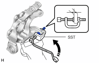
- Secure the rear axle carrier sub-assembly in a vise using aluminum plates.NOTE:
Do not overtighten the vise.
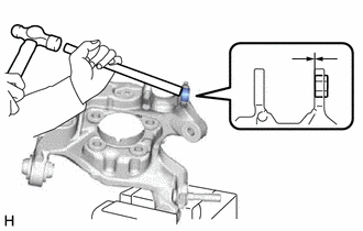
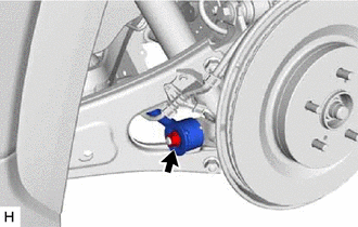
- Using a brass bar and a hammer, push out the bushing until it is positioned as shown in the illustration.
HINT:
Pushing out the bushing makes it easier to install the rear axle carrier sub-assembly.
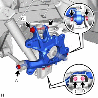
- Temporarily install the rear axle carrier sub-assembly to the rear No. 1 suspension arm assembly with the spacer and nut (A).NOTE:
Fully tighten the nut (A) after stabilizing the suspension.
- Temporarily install the rear axle carrier sub-assembly to the rear No. 2 suspension arm assembly with the bolt (B) and nut.NOTE:
- Insert the bolt with the threaded end facing the front of the vehicle.
- Because the nut has its own stopper, do not turn the nut. Tighten the bolt with the nut secured.
- Fully tighten the bolt (B) after stabilizing the suspension.
- Temporarily install the rear axle carrier sub-assembly to the rear upper control arm assembly with the bolt (C) and nut.NOTE:
- Insert the bolt with the threaded end facing the rear of the vehicle.
- Because the nut has its own stopper, do not turn the nut. Tighten the bolt with the nut secured.
- Fully tighten the bolt (C) after stabilizing the suspension.
- Install the rear axle carrier sub-assembly to the rear lower shock absorber bracket sub-assembly with the 2 bolts (D).
Torque: 147 N.m (1499 kgf/cm, 108 ft.lbf)
- Slowly lower the rear No. 2 suspension arm assembly.
- Secure the rear axle carrier sub-assembly in a vise using aluminum plates.
- INSTALL REAR TRAILING ARM ASSEMBLY
Refer to PROCEDURE - Step 1
- INSTALL REAR AXLE HUB AND BEARING ASSEMBLY
Refer to PROCEDURE - Step 1
- INSTALL REAR DISC
Refer to PROCEDURE - Step 1
- INSTALL REAR DISC BRAKE CYLINDER MOUNTING WITH BRAKE PAD
Refer to PROCEDURE - Step 10 [12/2019 - 10/2022] , or refer to PROCEDURE - Step 10 [10/2022 - 11/2023] , or refer to PROCEDURE - Step 10 [11/2023 - ]
- INSTALL REAR DISC BRAKE CYLINDER ASSEMBLY
Refer to PROCEDURE - Step 11 [12/2019 - 10/2022] , or refer to PROCEDURE - Step 11 [10/2022 - 11/2023] , or refer to PROCEDURE - Step 11 [11/2023 - ]
- INSTALL REAR SKID CONTROL SENSOR
Refer to PROCEDURE - Step 14
- INSTALL NO. 2 PARKING BRAKE WIRE ASSEMBLY
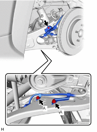
- Install the No. 2 parking brake wire assembly to the rear trailing arm assembly with the 3 bolts.
Bolt (A)
Torque: 15 N.m (153 kgf/cm, 11 ft.lbf)
Bolt (B)
Torque: 8.5 N.m (87 kgf/cm, 75 in.lbf)
- Install the No. 2 parking brake wire assembly to the rear axle carrier sub-assembly with the bolt.
Torque: 15 N.m (153 kgf/cm, 11 ft.lbf)
- Connect the No. 2 parking brake wire assembly connector to the rear skid control sensor.
- Connect the No. 2 parking brake wire assembly connector to the parking brake actuator assembly.
- Install the No. 2 parking brake wire assembly to the rear trailing arm assembly with the 3 bolts.
- INSTALL REAR FLEXIBLE HOSE
- Install the rear flexible hose to the rear upper control arm assembly with the bolt.
Torque: 18.8 N.m (192 kgf/cm, 14 ft.lbf)
- Install the rear flexible hose to the rear upper control arm assembly with the bolt.
- INSTALL REAR AXLE SHAFT NUT
- Clean the threaded parts on the rear drive shaft assembly and a new rear axle shaft nut using non-residue solvent.NOTE:
- Be sure to perform this work even when using a new rear drive shaft assembly.
- Keep the threaded parts free of oil and foreign matter.
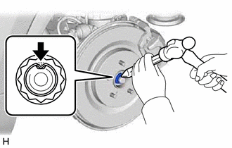
- Using a 30 mm deep socket wrench, temporarily install the rear axle shaft nut.
Torque: 294 N.m (2998 kgf/cm, 217 ft.lbf)
HINT:
Keep depressing the brake pedal to prevent the rear drive shaft assembly from rotating.
- Using a chisel and hammer, stake the rear axle shaft nut.
- Clean the threaded parts on the rear drive shaft assembly and a new rear axle shaft nut using non-residue solvent.
- STABILIZE SUSPENSION
Refer to PROCEDURE - Step 3
- INSTALL REAR UPPER CONTROL ARM ASSEMBLY
- Install the rear upper control arm assembly to the rear axle carrier sub-assembly with the bolt.
Torque: 110 N.m (1122 kgf/cm, 81 ft.lbf)
NOTE:Because the nut has its own stopper, do not turn the nut. Tighten the bolt with the nut secured.
- Install the rear upper control arm assembly to the rear axle carrier sub-assembly with the bolt.
- INSTALL REAR NO. 1 SUSPENSION ARM ASSEMBLY
- INSTALL REAR NO. 2 SUSPENSION ARM ASSEMBLY
- Install the rear No. 2 suspension arm assembly (rear axle carrier sub-assembly side) with the bolt.
Refer to PROCEDURE - Step 8 [12/2019 - 10/2022] , or refer to PROCEDURE - Step 8 [10/2022 - ]
- Install the rear No. 2 suspension arm assembly (rear axle carrier sub-assembly side) with the bolt.
- INSTALL REAR SUSPENSION ARM COVER
Refer to PROCEDURE - Step 9 [12/2019 - 10/2022] , or refer to PROCEDURE - Step 9 [10/2022 - ]
- INSTALL REAR WHEEL
Refer to PROCEDURE - Step 1 [12/2019 - 10/2022] , or refer to PROCEDURE - Step 1 [10/2022 - ]
- CONNECT CABLE TO NEGATIVE AUXILIARY BATTERY TERMINAL (for HV Model)
- Connect the reservoir level switch connector.
- Install the brake master cylinder reservoir assembly to the reservoir bracket with the bolt and nut.
Torque: 9.0 N.m (92 kgf/cm, 80 in.lbf)
- Engage the clamp to install the wire harness to the brake master cylinder reservoir assembly.
- Connect the cable to the negative (-) auxiliary battery terminal.
Refer to PROCEDURE - Step 2 [12/2019 - 11/2023] , or refer to PROCEDURE - Step 2 [11/2023 - ]
- Turn the ignition switch to ON (READY).
- Depress the brake pedal and release it.
- Clear the DTCs.
Refer to DTC CHECK / CLEAR [12/2019 - ]
- INSPECT AND ADJUST REAR WHEEL ALIGNMENT
Refer to ADJUSTMENT [12/2019 - 09/2020] , or refer to ADJUSTMENT [09/2020 - 10/2022] , or refer to ADJUSTMENT [10/2022 - 11/2023] , or refer to ADJUSTMENT [11/2023 - 11/2024] , or refer to ADJUSTMENT [11/2024 - ]
- CHECK FOR SPEED SENSOR SIGNAL
for HV Model: Refer to TEST MODE PROCEDURE [12/2019 - 11/2023] , or refer to TEST MODE PROCEDURE [11/2023 - ]
for Gasoline Model: Refer to TEST MODE PROCEDURE [12/2019 - 11/2023] , or refer to TEST MODE PROCEDURE [11/2023 - ]
- PERFORM INITIALIZATION
Parking Assist Monitor System Refer to CALIBRATION [12/2019 - 10/2022] , or refer to CALIBRATION [10/2022 - ] Panoramic View Monitor System Refer to CALIBRATION [12/2019 - 10/2022] , or refer to CALIBRATION [10/2022 - 11/2023] , or refer to CALIBRATION [11/2023 - ] Lighting System (EXT) (w/ AFS) Refer to INITIALIZATION [12/2019 - 11/2023] , or refer to INITIALIZATION [11/2023 - ]