Reassembly [12/2019 - ]: Procedure
- INSTALL BACK DOOR DAMPER STAY LOWER BRACKET LH
See step 2
- INSTALL BACK DOOR DAMPER STAY LOWER BRACKET RH
HINT:
Use the same procedure as for the LH side.
- INSTALL BACK DOOR STAY ASSEMBLY LH (w/o Power Back Door)
See step 4
- INSTALL BACK DOOR STAY ASSEMBLY RH (w/o Power Back Door)
HINT:
Use the same procedure as for the LH side.
- INSTALL POWER BACK DOOR UNIT SET ASSEMBLY LH (w/ Power Back Door)
See step 4
- INSTALL POWER BACK DOOR UNIT SET ASSEMBLY RH (w/ Power Back Door)
HINT:
Use the same procedure as for the LH side.
- INSTALL NO. 1 CAMERA CLEANER HOSE
- When replacing the back door panel sub-assembly:
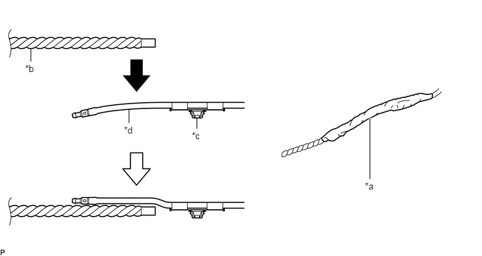
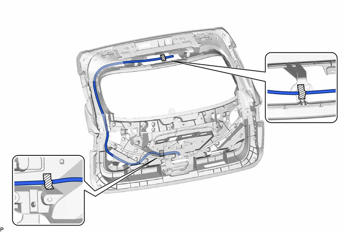
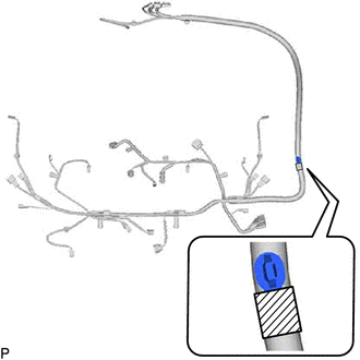
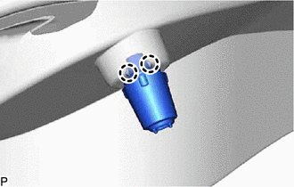
- Secure the rope with a diameter of 9.0 mm (0.354 in.) to the No. 1 camera cleaner hose with nonwoven tape as shown in the illustration.
*a Nonwoven Tape *b Rope *c Clamp *d Washer Hose NOTE:Make sure that the rope is secured with nonwoven tape to prevent the rope from separating from the No. 1 camera cleaner hose when removing it.
HINT:
- As the No. 1 camera cleaner hose is likely to be caught in the narrow areas inside the back door panel sub-assembly, make sure to align the clamp and washer hose in a straight line and cover the edges of the washer hose with nonwoven tape.
- A rope with a diameter of 8.0 mm (0.315 in.) or less may be caught in the gaps on the inside of the back door panel sub-assembly. Make sure to use a rope with a diameter of 9.0 mm (0.354 in.).
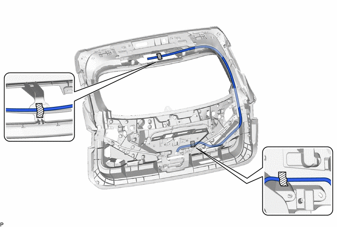
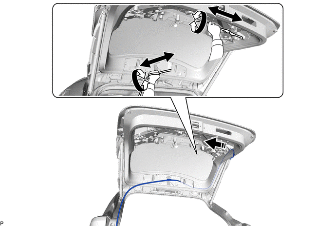
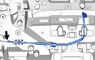
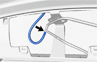
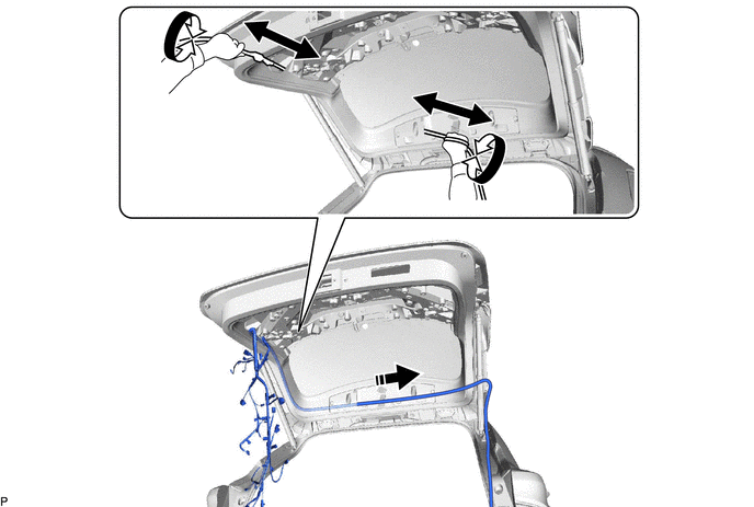
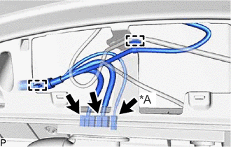
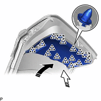
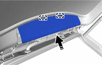
- Pass the No. 1 camera cleaner hose through the inside of the back door panel sub-assembly as shown in the illustration.

Install in this Direction - - NOTE:This step should not be performed with the back door panel sub-assembly removed from the vehicle.
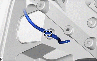
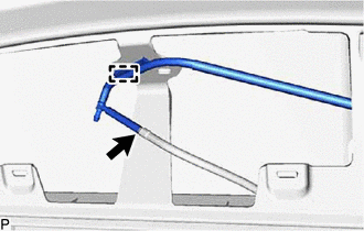
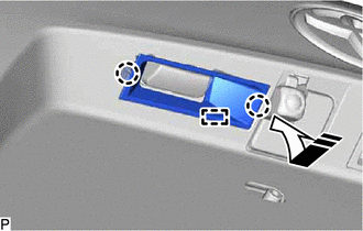
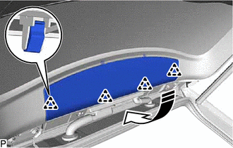
- Engage the clamp.
- Connect the washer hose.
- Engage the clamp to install the No. 1 camera cleaner hose.
- INSTALL NO. 2 CAMERA CLEANER HOSE
- INSTALL REAR WASHER (FROM JOINT TO NOZZLE) HOSE
- INSTALL REAR WASHER NOZZLE
Refer to PROCEDURE - Step 1
- INSTALL NO. 1 BACK DOOR WIRE
- When replacing the back door panel sub-assembly:
- When replacing the No. 1 back door wire:
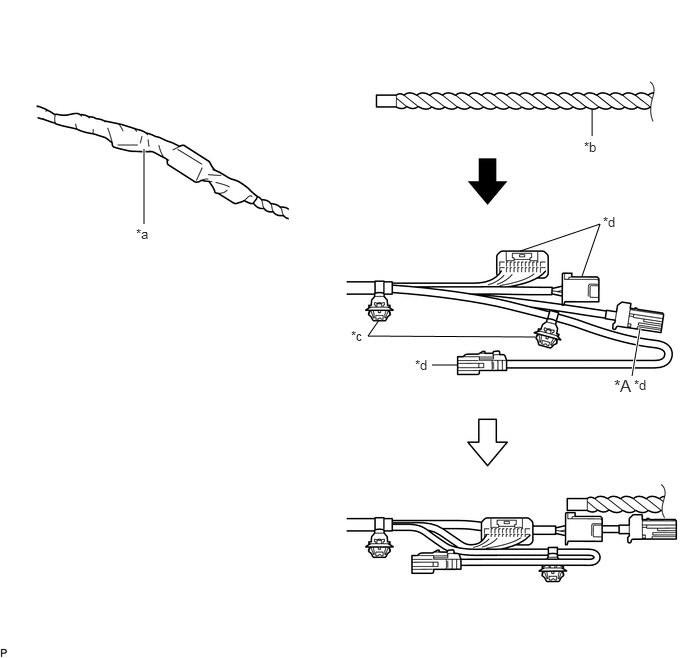
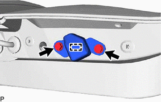
- Secure the rope with a diameter of 9.0 mm (0.354 in.) to the No. 1 back door wire with nonwoven tape as shown in the illustration.
*A w/ Digital Inner Mirror - - *a Nonwoven Tape *b Rope *c Clamp *d Connector NOTE:- As conduction performance may degrade if adhesive from the nonwoven tape contacts the connecting parts of the connectors, cover the connectors with a plastic bag or similar before applying the nonwoven tape.
- Make sure that the rope is secured with nonwoven tape to prevent the rope from separating from the No. 1 back door wire when removing it.
HINT:
- As the No. 1 back door wire is likely to be caught in the narrow areas inside the back door panel sub-assembly, make sure to align the clamp and connectors in a straight line and cover the edges of the connectors with nonwoven tape.
- A rope with a diameter of 8.0 mm (0.315 in.) or less may be caught in the gaps on the inside of the back door panel sub-assembly. Make sure to use a rope with a diameter of 9.0 mm (0.354 in.).
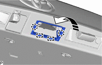
- Pass the No. 1 back door wire through the inside of the back door panel sub-assembly as shown in the illustration.
Install in this Direction - - NOTE:This step should not be performed with the back door panel sub-assembly removed from the vehicle.
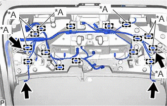
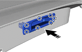
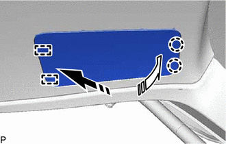
- Engage each clamp.
*A w/ Power Back Door - Connect each connector.
- Engage the 2 clamps.
*A w/ Digital Inner Mirror - Connect each connector to install the No. 1 back door wire.
- INSTALL TELEVISION CAMERA ASSEMBLY WITH NOZZLE (w/o Digital Inner Mirror)
Refer to PROCEDURE - Step 5
- INSTALL TELEVISION CAMERA ASSEMBLY WITH NOZZLE (w/ Digital Inner Mirror)
Refer to PROCEDURE - Step 6
- INSTALL CUSHION
- INSTALL BACK DOOR LOWER STOPPER LH
- INSTALL BACK DOOR LOWER STOPPER RH
HINT:
Use the same procedure for the RH side and LH side.
- INSTALL MULTIPLEX NETWORK DOOR ECU (w/ Power Back Door)
- INSTALL REAR LIGHT ASSEMBLY LH
Refer to PROCEDURE - Step 1
- INSTALL REAR LIGHT ASSEMBLY RH
HINT:
Use the same procedure as for the LH side.
- INSTALL POWER BACK DOOR SENSOR ASSEMBLY LH (w/ Power Back Door)
See step 1
- INSTALL POWER BACK DOOR SENSOR ASSEMBLY RH (w/ Power Back Door)
HINT:
Use the same procedure as for the LH side.
- INSTALL BACK DOOR LOCK ASSEMBLY (w/o Power Back Door)
Refer to PROCEDURE - Step 1
- INSTALL BACK DOOR LOCK ASSEMBLY WITH COURTESY LIGHT SWITCH (w/ Power Back Door)
Refer to PROCEDURE - Step 2
- INSTALL LICENSE PLATE LIGHT ASSEMBLY
HINT:
Use the same procedure for the RH side and LH side.
Refer to PROCEDURE - Step 3
- INSTALL NO. 1 BACK DOOR FINISH PANEL PROTECTOR
- INSTALL BACK DOOR OPENER SWITCH ASSEMBLY
See step 1
- INSTALL BACK DOOR FINISH PANEL COVER LH
- INSTALL BACK DOOR FINISH PANEL COVER RH
HINT:
Use the same procedure as for the LH side.
- INSTALL REAR NO. 3 SPEAKER ASSEMBLY (for 11 Speakers)
Refer to PROCEDURE - Step 1
- INSTALL REAR WIPER MOTOR GROMMET
Refer to PROCEDURE - Step 1
- INSTALL REAR WIPER MOTOR ASSEMBLY
Refer to PROCEDURE - Step 2
- INSTALL REAR WIPER ARM AND BLADE ASSEMBLY
Refer to PROCEDURE - Step 3
- INSTALL REAR WIPER ARM HEAD CAP
Refer to PROCEDURE - Step 4
- INSTALL DOOR PULL HANDLE
- INSTALL BACK DOOR TRIM PANEL ASSEMBLY
- INSTALL BACK DOOR SERVICE HOLE COVER LH
- INSTALL BACK DOOR SERVICE HOLE COVER RH
HINT:
Use the same procedure as for the LH side.
- INSTALL CENTER STOP LIGHT COVER
Refer to PROCEDURE - Step 1
- INSTALL CENTER STOP LIGHT GASKET
Refer to PROCEDURE - Step 2
- INSTALL CENTER STOP LIGHT ASSEMBLY
Refer to PROCEDURE - Step 3
- INSTALL DECK TRIM POCKET COVER PLATE
- INSPECT REAR WASHER NOZZLE
Refer to PROCEDURE - Step 1
- ADJUST REAR WASHER NOZZLE
Refer to PROCEDURE - Step 1
- INITIALIZE POWER BACK DOOR SYSTEM (w/ Power Back Door)
Refer to INITIALIZATION [12/2019 - 11/2023] , or refer to INITIALIZATION [11/2023 - ]
- INSPECT POWER BACK DOOR SYSTEM (w/ Power Back Door)
Refer to OPERATION CHECK [12/2019 - 11/2023] , or refer to OPERATION CHECK [11/2023 - ]
- PERFORM CALIBRATION (w/ Parking Assist Monitor System)
Refer to CALIBRATION [12/2019 - 10/2022] , or refer to CALIBRATION [10/2022 - ]
- PERFORM CALIBRATION (w/ Panoramic View Monitor System)
Refer to CALIBRATION [12/2019 - 10/2022] , or refer to CALIBRATION [10/2022 - 11/2023] , or refer to CALIBRATION [11/2023 - ]
- ADJUST BACK DOOR
HINT:
When the back door damper stay lower bracket is removed, it is necessary to perform back door position adjustment.
Refer to ADJUSTMENT [12/2019 - ]