Installation [12/2019 - 10/2022]: Procedure
- INSTALL WATER FILLER BRACKET
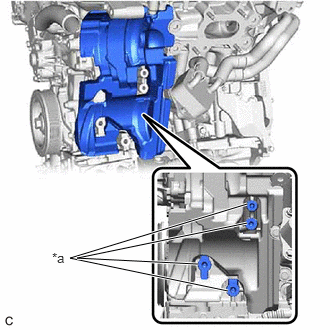
- Temporarily install the water filler bracket to the camshaft housing sub-assembly LH with the 2 bolts.
 Courtesy of © TOYOTA, LICENSE AGREEMENT TMS1002
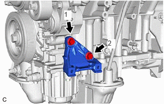
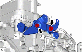
*a Stopper *b Protrusion - Fully tighten the 2 bolts in the order shown in the illustration.
Torque: 8.0 N.m (82 kgf/cm, 71 in.lbf)
NOTE:Make sure that the stopper of the water filler bracket is pressed against the protrusion of the camshaft housing sub-assembly LH when fully tightening the 2 bolts.
- Temporarily install the water filler bracket to the camshaft housing sub-assembly LH with the 2 bolts.
- INSTALL WIRE HARNESS CLAMP BRACKET
- Install the wire harness clamp bracket to the camshaft housing sub-assembly with the bolt.
Torque: 30 N.m (306 kgf/cm, 22 ft.lbf)
- Install the wire harness clamp bracket to the camshaft housing sub-assembly LH with the bolt.
Torque: 30 N.m (306 kgf/cm, 22 ft.lbf)
- Install the wire harness clamp bracket to the camshaft housing sub-assembly with the bolt.
- INSTALL DRIVE SHAFT BEARING BRACKET
- Install the drive shaft bearing bracket to the cylinder block sub-assembly with the 3 bolts.
Torque: 63.7 N.m (650 kgf/cm, 47 ft.lbf)
NOTE:Make sure that there is no oil on the threads of the bolts.
- Install the drive shaft bearing bracket to the cylinder block sub-assembly with the 3 bolts.
- INSTALL NO. 5 CYLINDER BLOCK INSULATOR
- INSTALL ENGINE OIL LEVEL DIPSTICK GUIDE
- Install a new engine oil level dipstick guide O-ring to the engine oil level dipstick guide.
- Apply a light coat of engine oil to the engine oil level dipstick guide O-ring.
- Insert the engine oil level dipstick guide end into the oil pan sub-assembly.
- Install the engine oil level dipstick guide to the camshaft housing sub-assembly LH with the bolt.
Torque: 21 N.m (214 kgf/cm, 15 ft.lbf)
- Install the engine oil level dipstick to the engine oil level dipstick guide.
- INSTALL WATER PUMP PULLEY
Refer to PROCEDURE - Step 2
- INSTALL V-RIBBED BELT TENSIONER ASSEMBLY
- Install the V-ribbed belt tensioner assembly with the 2 bolts.
Torque: 43 N.m (438 kgf/cm, 32 ft.lbf)
- Install the V-ribbed belt tensioner assembly with the 2 bolts.
- INSTALL NO. 2 IDLER PULLEY SUB-ASSEMBLY
Refer to PROCEDURE - Step 3
- INSTALL NO. 1 COMPRESSOR MOUNTING BRACKET
- Temporarily install the No. 1 compressor mounting bracket to the cylinder block sub-assembly with the 2 bolts.
- Fully tighten the 2 bolts in the order shown in the illustration.
Torque: 43 N.m (438 kgf/cm, 32 ft.lbf)
- INSTALL COMPRESSOR AND MAGNETIC CLUTCH
Refer to PROCEDURE - Step 2
- INSTALL GENERATOR ASSEMBLY
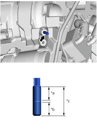
- w/ Stud Bolt
*a 14 mm (0.551 in.) *b 13 mm (0.512 in.) *c 29 mm (1.14 in.) - Using an E8 "TORX" socket wrench, install the stud bolt to the cylinder block sub-assembly.
Torque: 6.0 N.m (61 kgf/cm, 53 in.lbf)
- Using an E8 "TORX" socket wrench, install the stud bolt to the cylinder block sub-assembly.
- Install the generator assembly.
Refer to PROCEDURE - Step 1
- w/ Stud Bolt
- INSTALL V-RIBBED BELT
Refer to PROCEDURE - Step 1
- INSTALL NO. 2 VENTILATION HOSE
- Install the No. 2 ventilation hose to the cylinder head cover sub-assembly and slide the clip to secure it.
- INSTALL VENTILATION HOSE
- Install the ventilation hose to the PCV valve (ventilation valve sub-assembly) and slide the clip to secure it.
- INSTALL NO. 2 WATER BY-PASS HOSE
- Install the No. 2 water by-pass hose to the water outlet and slide the clip to secure it.
- INSTALL NO. 3 WATER BY-PASS HOSE
- Install the No. 3 water by-pass hose to the water inlet pipe and slide the clip to secure it.
- INSTALL WATER BY-PASS HOSE ASSEMBLY
- Install the water by-pass hose assembly to the water inlet pipe and slide the clip to secure it.
- INSTALL VACUUM PUMP ASSEMBLY
Refer to PROCEDURE - Step 1
- INSTALL IGNITION COIL ASSEMBLY
Refer to PROCEDURE - Step 2
- INSTALL SENSOR WIRE
- Engage the 2 clamps and install the sensor wire with the bolt.
Torque: 10 N.m (102 kgf/cm, 7 ft.lbf)
- Engage the 2 clamps and install the sensor wire with the bolt.
- INSTALL KNOCK CONTROL SENSOR
Refer to INSTALLATION [12/2019 - 10/2022]