Installation [10/2022 - ]: Procedure
- INSTALL HOLE PLUG
- INSTALL REAR SUSPENSION MEMBER FRONT BODY MOUNTING CUSHION (for LH Side)
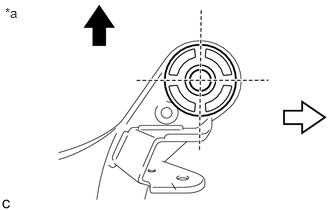
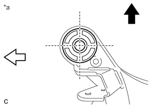
- Confirm the installation direction and temporarily install a new rear suspension member front body mounting cushion.NOTE:
- Position the rear suspension member front body mounting cushion in the correct direction.
- Do not apply lubricant to the outer sleeve of the rear suspension member front body mounting cushion.
*a View from Underneath 
Front of the Vehicle 
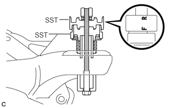
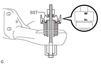
Outside of the Vehicle - Install SST as shown in the illustration.
- SST: 09527-17011
- SST: 09830-10010
- 09830-01010
- 09830-01020
- 09830-01030
- 09830-01060
NOTE:Apply molybdenum grease to the threads and tip of the SST center bolt before use.
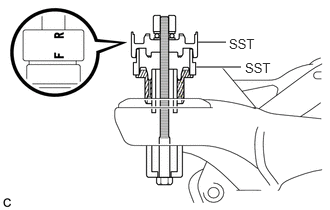
HINT:
Use SST with the "F" mark facing the rear suspension member front body mounting cushion.
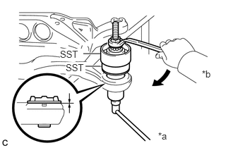
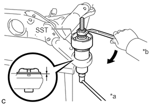
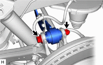
- Using SST, install the rear suspension member front body mounting cushion until there is no clearance between the rear suspension member sub-assembly and rear suspension member front body mounting cushion.
- SST: 09527-17011
- SST: 09830-10010
- 09830-01010
- 09830-01020
- 09830-01030
- 09830-01060
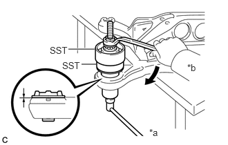
NOTE:If the rear suspension member sub-assembly is scratched, apply paint to the scratched areas of the rear suspension member sub-assembly.
*a Hold *b Turn - Remove SST from the rear suspension member sub-assembly.
- Confirm the installation direction and temporarily install a new rear suspension member front body mounting cushion.
- INSTALL REAR SUSPENSION MEMBER FRONT BODY MOUNTING CUSHION (for RH Side)
- Confirm the installation direction and temporarily install a new rear suspension member front body mounting cushion.NOTE:
- Position the rear suspension member front body mounting cushion in the correct direction.
- Do not apply lubricant to the outer sleeve of the rear suspension member front body mounting cushion.
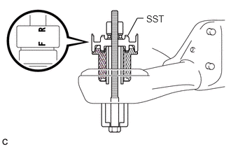
*a View from Underneath Front of the Vehicle Outside of the Vehicle - Install SST as shown in the illustration.
- SST: 09527-17011
- SST: 09830-10010
- 09830-01010
- 09830-01020
- 09830-01030
- 09830-01060
NOTE:Apply molybdenum grease to the threads and tip of the SST center bolt before use.
HINT:
Use SST with the "F" mark facing the rear suspension member front body mounting cushion.
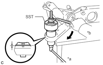
- Using SST, install the rear suspension member front body mounting cushion until there is no clearance between the rear suspension member sub-assembly and rear suspension member front body mounting cushion.
- SST: 09527-17011
- SST: 09830-10010
- 09830-01010
- 09830-01020
- 09830-01030
- 09830-01060
NOTE:If the rear suspension member sub-assembly is scratched, apply paint to the scratched areas of the rear suspension member sub-assembly.
*a Hold *b Turn - Remove SST from the rear suspension member sub-assembly.
- Confirm the installation direction and temporarily install a new rear suspension member front body mounting cushion.
- INSTALL REAR SUSPENSION MEMBER REAR BODY MOUNT CUSHION LH
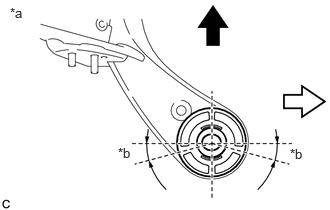
- Confirm the installation direction and temporarily install a new rear suspension member rear body mount cushion LH.NOTE:
- Position the rear suspension member rear body mount cushion LH in the correct direction.
- Do not apply lubricant to the outer sleeve of the rear suspension member rear body mount cushion LH.
*a View from Underneath *b 15° Front of the Vehicle Outside of the Vehicle - Install SST as shown in the illustration.
- SST: 09830-10010
- 09830-01010
- 09830-01020
- 09830-01030
- 09830-01060
NOTE:Apply molybdenum grease to the threads and tip of the SST center bolt before use.
HINT:
Use SST with the "F" mark facing the rear suspension member rear body mount cushion LH.
- SST: 09830-10010
- Using SST, install the rear suspension member rear body mount cushion LH until there is no clearance between the rear suspension member sub-assembly and rear suspension member rear body mount cushion LH.
- SST: 09830-10010
- 09830-01010
- 09830-01020
- 09830-01030
- 09830-01060
NOTE:If the rear suspension member sub-assembly is scratched, apply paint to the scratched areas of the rear suspension member sub-assembly.
*a Hold *b Turn - SST: 09830-10010
- Remove SST from the rear suspension member sub-assembly.
- Confirm the installation direction and temporarily install a new rear suspension member rear body mount cushion LH.
- INSTALL REAR SUSPENSION MEMBER REAR BODY MOUNT CUSHION RH
- Confirm the installation direction and temporarily install a new rear suspension member rear body mount cushion RH.NOTE:
- Position the rear suspension member rear body mount cushion RH in the correct direction.
- Do not apply lubricant to the outer sleeve of the rear suspension member rear body mount cushion RH.
*a View from Underneath Front of the Vehicle Outside of the Vehicle - Install SST as shown in the illustration.
- SST: 09830-10010
- 09830-01010
- 09830-01020
- 09830-01030
- 09830-01060
NOTE:Apply molybdenum grease to the threads and tip of the SST center bolt before use.
HINT:
Use SST with the "F" mark facing the rear suspension member rear body mount cushion RH.
- SST: 09830-10010
- Using SST, install the rear suspension member rear body mount cushion RH until there is no clearance between the rear suspension member sub-assembly and rear suspension member rear body mount cushion RH.
- SST: 09830-10010
- 09830-01010
- 09830-01020
- 09830-01030
- 09830-01060
NOTE:If the rear suspension member sub-assembly is scratched, apply paint to the scratched areas of the rear suspension member sub-assembly.
*a Hold *b Turn - SST: 09830-10010
- Remove SST from the rear suspension member sub-assembly.
- Confirm the installation direction and temporarily install a new rear suspension member rear body mount cushion RH.
- INSTALL REAR UPPER CONTROL ARM ASSEMBLY LH
See step 1
- INSTALL REAR UPPER CONTROL ARM ASSEMBLY RH
HINT:
Perform the same procedure as for the LH side.
- INSTALL REAR SUSPENSION MEMBER UPPER STOPPER
- Install the 2 rear suspension member upper stoppers to the rear suspension member sub-assembly.
- INSTALL REAR SUSPENSION MEMBER LOWER STOPPER RETAINER
- Install the 2 rear suspension member lower stopper retainers to the rear suspension member sub-assembly.
- INSTALL REAR SUSPENSION MEMBER SUB-ASSEMBLY
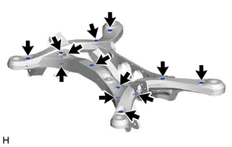
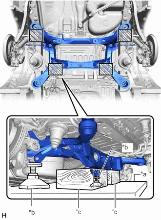
- Using an engine lifter, 2 attachments and 2 wooden blocks or equivalent tools, support the rear suspension member sub-assembly, and raise the rear suspension member sub-assembly until there is no clearance between the rear suspension member sub-assembly and vehicle body.
*a Engine Lifter *b Attachment *c Wooden Block 
Attachment and Wooden Block Placement Location WARNING:- The rear suspension member sub-assembly is a very heavy component. Make sure that it is supported securely.
- If the rear suspension member sub-assembly is not securely supported, it may drop, resulting in serious injury.
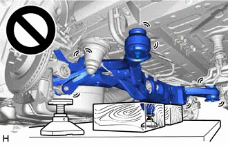
NOTE:- Use attachments and wooden blocks to keep the rear suspension member sub-assembly level.
- Keep supporting the rear suspension member sub-assembly until the installation has been completed.
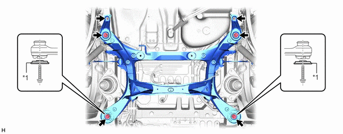
- Install the rear suspension member sub-assembly with the 2 rear lower suspension braces, rear lower suspension member stopper LH and rear lower suspension member stopper RH, with the 4 bolts and 2 nuts.
*1 Rear Lower Suspension Brace - - Bolt
Torque: 158 N.m (1611 kgf/cm, 117 ft.lbf)
Nut
Torque: 32 N.m (326 kgf/cm, 24 ft.lbf)
NOTE:Be sure to install the rear suspension member sub-assembly with the rear lower suspension braces facing in the correct direction as shown in the illustration.
- Using an engine lifter, 2 attachments and 2 wooden blocks or equivalent tools, support the rear suspension member sub-assembly, and raise the rear suspension member sub-assembly until there is no clearance between the rear suspension member sub-assembly and vehicle body.
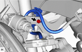
- INSTALL FRAME WIRE (w/ Wire Harness)
- w/ Height Control Sensor:
- Engage the clamp.
- Install the frame wire to the rear suspension member sub-assembly with the nut.
Torque: 8.0 N.m (82 kgf/cm, 71 in.lbf)
- for AWD:
- Install the frame wire to the rear suspension member sub-assembly with the bolt and clamp.
Torque: 8.0 N.m (82 kgf/cm, 71 in.lbf)
- Install the frame wire to the rear suspension member sub-assembly with the bolt and clamp.
- for 2WD:
- Install the frame wire to the rear suspension member sub-assembly with the bolt.
Torque: 8.0 N.m (82 kgf/cm, 71 in.lbf)
- Install the frame wire to the rear suspension member sub-assembly with the bolt.
- w/ Height Control Sensor:
- INSTALL REAR NO. 1 DIFFERENTIAL MOUNT CUSHION (for AWD)
Refer to PROCEDURE - Step 1
- INSTALL REAR DIFFERENTIAL CARRIER ASSEMBLY (for Dynamic Torque Control AWD)
Refer to PROCEDURE - Step 4
- INSTALL TORQUE VECTORING DIFFERENTIAL CARRIER ASSEMBLY (for Dynamic Torque Vectoring AWD)
Refer to PROCEDURE - Step 5
- INSTALL REAR DRIVE SHAFT LH SNAP RING (for AWD)
Refer to PROCEDURE - Step 1
- INSTALL REAR DRIVE SHAFT RH SNAP RING (for AWD)
HINT:
Use the same procedure as for the rear drive shaft LH snap ring.
- INSTALL REAR DRIVE SHAFT ASSEMBLY LH (for AWD)
Refer to PROCEDURE - Step 2
- INSTALL REAR DRIVE SHAFT ASSEMBLY RH (for AWD)
HINT:
Perform the same procedure as for the LH side.
- TEMPORARILY INSTALL REAR UPPER CONTROL ARM ASSEMBLY LH
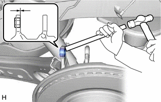
- Using a brass bar and a hammer, push out the bushing until it is positioned as shown in the illustration.
HINT:
Pushing out the bushing makes it easier to connect the rear upper control arm assembly LH.
- Temporarily install the rear axle carrier sub-assembly to the rear upper control arm assembly with the bolt and nut.NOTE:
- Insert the bolt with the threaded end facing the rear of the vehicle.
- Because the nut has its own stopper, do not turn the nut. Tighten the bolt with the nut secured.
- Using a brass bar and a hammer, push out the bushing until it is positioned as shown in the illustration.
- TEMPORARILY INSTALL REAR UPPER CONTROL ARM ASSEMBLY RH
HINT:
Perform the same procedure as for the LH side.
- TEMPORARILY INSTALL REAR NO. 1 SUSPENSION ARM ASSEMBLY LH
See step 1
- TEMPORARILY INSTALL REAR NO. 1 SUSPENSION ARM ASSEMBLY RH
HINT:
Perform the same procedure as for the LH side.
- TEMPORARILY INSTALL REAR NO. 2 SUSPENSION ARM ASSEMBLY LH
See step 2
- TEMPORARILY INSTALL REAR NO. 2 SUSPENSION ARM ASSEMBLY RH
HINT:
Perform the same procedure as for the LH side.
- INSTALL REAR LOWER COIL SPRING INSULATOR LH
See step 3
- INSTALL REAR LOWER COIL SPRING INSULATOR RH
HINT:
Perform the same procedure as for the LH side.
- INSTALL REAR COIL SPRING LH
See step 4
- INSTALL REAR COIL SPRING RH
HINT:
Perform the same procedure as for the LH side.
- INSTALL REAR LOWER STABILIZER BRACKET
See step 3
- INSTALL REAR STABILIZER BAR
See step 4
- TEMPORARILY INSTALL REAR STABILIZER LINK ASSEMBLY LH
See step 5
- TEMPORARILY INSTALL REAR STABILIZER LINK ASSEMBLY RH
HINT:
Perform the same procedure as for the LH side.
- INSTALL REAR SKID CONTROL SENSOR LH (for AWD)
Refer to PROCEDURE - Step 14
- INSTALL REAR SKID CONTROL SENSOR RH (for AWD)
HINT:
Perform the same procedure as for the LH side.
- CONNECT NO. 2 PARKING BRAKE WIRE ASSEMBLY (for AWD)
- Connect the No. 2 parking brake wire assembly connector to the rear skid control sensor.
- CONNECT NO. 1 PARKING BRAKE WIRE ASSEMBLY (for AWD)
HINT:
Perform the same procedure as for the LH side.
- INSTALL REAR AXLE SHAFT NUT LH (for AWD)
Refer to PROCEDURE - Step 11
- INSTALL REAR AXLE SHAFT NUT RH (for AWD)
HINT:
Perform the same procedure as for the LH side.
- INSTALL REAR HEIGHT CONTROL SENSOR SUB-ASSEMBLY LH (w/ Height Control Sensor)
Refer to INSTALLATION [12/2019 - ]
- CONNECT REAR FLEXIBLE HOSE LH
- CONNECT REAR FLEXIBLE HOSE RH
HINT:
Perform the same procedure as for the LH side.
- STABILIZE SUSPENSION
See step 3
- INSTALL REAR NO. 1 SUSPENSION ARM ASSEMBLY LH
See step 7
- INSTALL REAR NO. 1 SUSPENSION ARM ASSEMBLY RH
HINT:
Perform the same procedure as for the LH side.
- INSTALL REAR NO. 2 SUSPENSION ARM ASSEMBLY LH
- Install the rear No. 2 suspension arm assembly LH (rear axle carrier sub-assembly side) with the bolt.
See step 8
- Install the rear No. 2 suspension arm assembly LH (rear axle carrier sub-assembly side) with the bolt.
- INSTALL REAR NO. 2 SUSPENSION ARM ASSEMBLY RH
HINT:
Perform the same procedure as for the LH side.
- INSTALL REAR STABILIZER LINK ASSEMBLY LH
See step 8
- INSTALL REAR STABILIZER LINK ASSEMBLY RH
HINT:
Perform the same procedure as for the LH side.
- INSTALL REAR UPPER CONTROL ARM ASSEMBLY LH
- Install the rear upper control arm assembly to the rear axle carrier sub-assembly with the bolt.
Torque: 110 N.m (1122 kgf/cm, 81 ft.lbf)
NOTE:Because the nut has its own stopper, do not turn the nut. Tighten the bolt with the nut secured.
- Install the rear upper control arm assembly to the rear axle carrier sub-assembly with the bolt.
- INSTALL REAR UPPER CONTROL ARM ASSEMBLY RH
HINT:
Perform the same procedure as for the LH side.
- INSTALL REAR SUSPENSION ARM COVER LH
See step 9
- INSTALL REAR SUSPENSION ARM COVER RH
HINT:
Perform the same procedure as for the LH side.
- INSTALL PROPELLER WITH CENTER BEARING SHAFT ASSEMBLY (for AWD)
Refer to INSTALLATION [10/2022 - ]
- INSTALL TAIL EXHAUST PIPE ASSEMBLY
Refer to INSTALLATION [10/2022 - ]
- INSTALL REAR WHEEL
Refer to PROCEDURE - Step 1
- INSTALL REAR NO. 2 SUSPENSION ARM ASSEMBLY LH
- Install the rear No. 2 suspension arm assembly LH (rear suspension member sub-assembly side) with the nut.
See step 12
- Install the rear No. 2 suspension arm assembly LH (rear suspension member sub-assembly side) with the nut.
- INSTALL REAR NO. 2 SUSPENSION ARM ASSEMBLY RH
HINT:
Perform the same procedure as for the LH side.
- ADD DIFFERENTIAL OIL (for AWD)
for Dynamic Torque Control AWD: Refer to PROCEDURE - Step 3
for Dynamic Torque Vectoring AWD: Refer to PROCEDURE - Step 4
- INSPECT FOR DIFFERENTIAL OIL LEAK (for AWD)
- INSPECT FOR EXHAUST GAS LEAK
Refer to PROCEDURE - Step 3
- INSPECT AND ADJUST REAR WHEEL ALIGNMENT
Refer to ADJUSTMENT [10/2022 - 11/2023] , or refer to ADJUSTMENT [11/2023 - 11/2024] , or refer to ADJUSTMENT [11/2024 - ]
- CHECK FOR SPEED SENSOR SIGNAL (for AWD)
Refer to TEST MODE PROCEDURE [12/2019 - 11/2023] , or refer to TEST MODE PROCEDURE [11/2023 - ]
- PERFORM INITIALIZATION
Parking Assist Monitor System Refer to CALIBRATION [10/2022 - ] Panoramic View Monitor System Refer to CALIBRATION [10/2022 - 11/2023] , or refer to CALIBRATION [11/2023 - ] Lighting System (EXT) (w/ AFS) Refer to INITIALIZATION [12/2019 - 11/2023] , or refer to INITIALIZATION [11/2023 - ]