Installation [12/2019 - 10/2022]: Procedure
- INSTALL REAR COOLING UNIT ASSEMBLY
- for Gasoline Model:
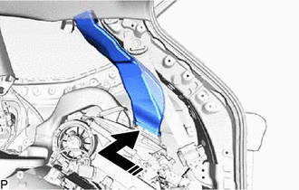
- Engage the guide.
 Courtesy of © TOYOTA, LICENSE AGREEMENT TMS1002
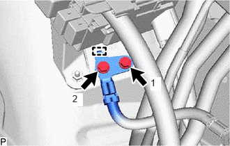
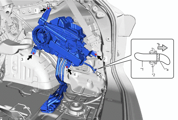
*1 Drain Cooler Hose *2 Drain Hose Grommet *a Marking *b Insert - Install the rear cooling unit assembly with the 4 bolts.
Torque: 9.8 N.m (100 kgf/cm, 87 in.lbf)
NOTE:Tighten the bolts in the order shown in the illustration to install the rear cooling unit assembly.
- Connect the drain cooler hose as shown in the illustration.
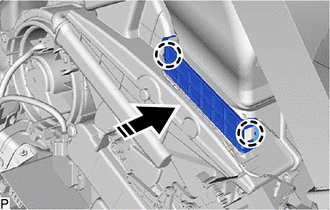
- Engage each clamp.
- Connect each connector.
- Engage the guide.
- for HV Model:
- Engage the guide.
 Courtesy of © TOYOTA, LICENSE AGREEMENT TMS1002
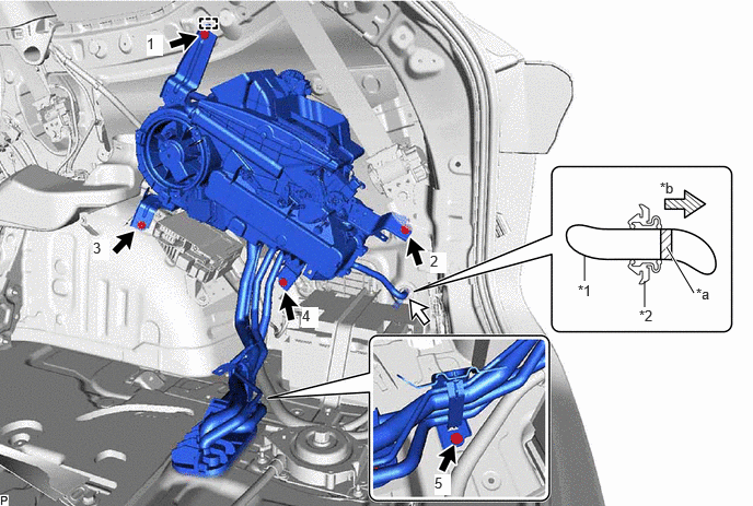
*1 Drain Cooler Hose *2 Drain Hose Grommet *a Marking *b Insert - Install the rear cooling unit assembly with the 5 bolts.
Torque: 9.8 N.m (100 kgf/cm, 87 in.lbf)
NOTE:Tighten the bolts in the order shown in the illustration to install the rear cooling unit assembly.
- Connect the drain cooler hose as shown in the illustration.
- Engage each clamp.
- Connect each connector.
- Engage the guide.
- Connect the earth wire with the 2 bolts.
Torque: 10 N.m (102 kgf/cm, 7 ft.lbf)
NOTE:Tighten the bolts in the order shown in the illustration.
- Engage the guide.
- Install the 2 bolts.
Torque: 5.4 N.m (55 kgf/cm, 48 in.lbf)
- for Gasoline Model:
- CONNECT NO. 2 AIR CONDITIONING ACCESSORY ASSEMBLY
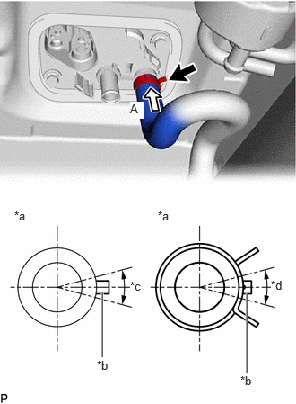
- Connect the inlet heater water hose with the marking within the area shown in the illustration.
*a View A *b Marking (White) *c Inlet Heater Water Hose Installation Angle (30°) *d Clip Installation Angle (60°) NOTE:Do not apply excessive force to the inlet heater water hose.
- Engage the clip within the area shown in the illustration.
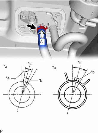
- Connect the outlet heater water hose with the marking within the area shown in the illustration.
*a View A *b Marking (Yellow) *c Outlet Heater Water Hose Installation Angle (30°) *d Clip Installation Angle (60°) *e 15° NOTE:Do not apply excessive force to the outlet heater water hose.
- Engage the clip within the area shown in the illustration.
- Remove the vinyl tape from the suction tube.
- Sufficiently apply compressor oil to a new O-ring and the fitting surface of the suction tube.
Refrigerant Compressor Oil for Gasoline Model ND-OIL 12 or equivalent for HV Model ND-OIL 11 or equivalent - Install the O-ring to the suction tube.NOTE:
Keep the O-rings and O-ring fitting surfaces free of foreign matter.
- Connect the suction tube with the bolt.
Torque: 5.4 N.m (55 kgf/cm, 48 in.lbf)
- Remove the vinyl tape from the liquid tube.
- Sufficiently apply compressor oil to a new O-ring and the fitting surface of the liquid tube.
Refrigerant Compressor Oil for Gasoline Model ND-OIL 12 or equivalent for HV Model ND-OIL 11 or equivalent - Install the O-ring to the liquid tube.NOTE:
Keep the O-rings and O-ring fitting surfaces free of foreign matter.
- Connect the liquid tube with the bolt.
Torque: 5.4 N.m (55 kgf/cm, 48 in.lbf)
- Install the spare tire.
- Connect the inlet heater water hose with the marking within the area shown in the illustration.
- INSTALL REAR NO. 3 SIDE AIR DUCT
- INSTALL REAR NO. 1 SIDE AIR DUCT
- INSTALL COOLER PLATE
- INSTALL INNER ROOF SIDE GARNISH ASSEMBLY RH
HINT:
Use the same procedure as for the LH side.
Refer to PROCEDURE - Step 21
- INSTALL QUARTER PILLAR GARNISH RH
HINT:
Use the same procedure as for the LH side.
Refer to PROCEDURE - Step 22
- INSTALL DECK TRIM SIDE PANEL ASSEMBLY RH
Refer to PROCEDURE - Step 33
- INSTALL ROPE HOOK (for RH Side)
HINT:
Use the same procedure as for the LH side.
Refer to PROCEDURE - Step 24
- INSTALL NO. 1 LUGGAGE COMPARTMENT TRIM HOOK (for RH Side)
HINT:
Use the same procedure as for the LH side.
Refer to PROCEDURE - Step 25
- INSTALL DECK TRIM POCKET COVER (for RH Side)
HINT:
Use the same procedure as for the LH side.
Refer to PROCEDURE - Step 26
- INSTALL COOLER (NO. 2 ROOM TEMP. SENSOR) THERMISTOR (w/ Rear Automatic Air Conditioning System)
Refer to PROCEDURE - Step 1
- CONNECT REAR NO. 2 SEAT OUTER BELT ASSEMBLY RH
HINT:
Use the same procedure as for the LH side.
Refer to PROCEDURE - Step 9
- INSTALL NO. 1 DECK SIDE TRIM COVER
HINT:
Use the same procedure as for the No. 2 deck side trim cover.
Refer to PROCEDURE - Step 28
- CONNECT REAR SEAT OUTER BELT ASSEMBLY RH
HINT:
Use the same procedure as for the LH side.
Refer to PROCEDURE - Step 11 [12/2019 - 10/2021] , or refer to PROCEDURE - Step 11 [10/2021 - ]
- INSTALL FRONT DECK SIDE TRIM COVER RH
Refer to PROCEDURE - Step 41
- CONNECT REAR DOOR OPENING TRIM WEATHERSTRIP RH
Refer to PROCEDURE - Step 1
- INSTALL REAR DOOR SCUFF PLATE RH
HINT:
Use the same procedure as for the LH side.
Refer to PROCEDURE - Step 47
- INSTALL REAR OUTER SEAT TRACK BRACKET COVER RH
HINT:
Use the same procedure as for the LH side.
Refer to PROCEDURE - Step 48
- INSTALL REAR NO. 2 SEAT ASSEMBLY
Refer to INSTALLATION [12/2019 - ]
- INSTALL REAR FLOOR FINISH PLATE
Refer to PROCEDURE - Step 65
- ADD ENGINE COOLANT (for Gasoline Model)
Refer to PROCEDURE - Step 2
- INSPECT FOR COOLANT LEAK (for Gasoline Model)
Refer to PROCEDURE - Step 1
- ADD ENGINE COOLANT (for HV Model)
for Engine:
Refer to PROCEDURE - Step 2
- INSPECT FOR COOLANT LEAK (for HV Model)
for Engine:
Refer to PROCEDURE - Step 1
- CHARGE AIR CONDITIONING SYSTEM WITH REFRIGERANT
Refer to PROCEDURE - Step 2
- WARM UP ENGINE (for Gasoline Model)
Refer to PROCEDURE - Step 3
- WARM UP COMPRESSOR (for HV Model)
Refer to PROCEDURE - Step 4
- INSPECT FOR REFRIGERANT LEAK
Refer to PROCEDURE - Step 5