Removal [12/2019 - 10/2022]: Procedure
- INSTALL ENGINE ASSEMBLY TO ENGINE STAND
Refer to REMOVAL [12/2019 - 09/2020] , or refer to REMOVAL [09/2020 - 10/2022]
- REMOVE ENGINE HANGERS
See step 70 [12/2019 - 09/2020], or see step 70 [09/2020 - 10/2022]
- REMOVE THROTTLE BODY WITH MOTOR ASSEMBLY
Refer to REMOVAL [12/2019 - 10/2022]
- DISCONNECT VENTILATION HOSE
Refer to PROCEDURE - Step 14
- DISCONNECT PURGE VALVE (PURGE VSV)
Refer to PROCEDURE - Step 15
- REMOVE NO. 2 SURGE TANK STAY
Refer to PROCEDURE - Step 16
- REMOVE INTAKE AIR SURGE TANK ASSEMBLY
Refer to PROCEDURE - Step 17
- REMOVE AIR SURGE TANK TO INTAKE MANIFOLD GASKET
Refer to PROCEDURE - Step 18
- REMOVE IGNITION COIL ASSEMBLY
Refer to PROCEDURE - Step 2
- REMOVE VACUUM PUMP ASSEMBLY
Refer to PROCEDURE - Step 11
- REMOVE ENGINE OIL LEVEL DIPSTICK GUIDE
Refer to PROCEDURE - Step 17
- REMOVE WIRE HARNESS CLAMP BRACKET
Refer to PROCEDURE - Step 20
- REMOVE WATER FILLER BRACKET
Refer to PROCEDURE - Step 21
- REMOVE CAMSHAFT TIMING OIL CONTROL SOLENOID ASSEMBLY (for Intake Side of Bank 1)
Refer to PROCEDURE - Step 3
- REMOVE CAMSHAFT TIMING OIL CONTROL SOLENOID ASSEMBLY (for Exhaust Side of Bank 1)
Refer to PROCEDURE - Step 5
- REMOVE CAMSHAFT TIMING OIL CONTROL SOLENOID ASSEMBLY (for Exhaust Side of Bank 2)
Refer to PROCEDURE - Step 2
- REMOVE CAMSHAFT TIMING OIL CONTROL SOLENOID ASSEMBLY (for Intake Side of Bank 2)
Refer to PROCEDURE - Step 7
- REMOVE VVT SENSOR (for Intake Side of Bank 1)
Refer to PROCEDURE - Step 2
- REMOVE VVT SENSOR (for Exhaust Side of Bank 1)
Refer to PROCEDURE - Step 3
- REMOVE VVT SENSOR (for Intake Side of Bank 2)
Refer to PROCEDURE - Step 4
- REMOVE VVT SENSOR (for Exhaust Side of Bank 2)
Refer to PROCEDURE - Step 5
- REMOVE CYLINDER HEAD COVER SUB-ASSEMBLY
Refer to PROCEDURE - Step 25
- REMOVE CYLINDER HEAD COVER SUB-ASSEMBLY LH
Refer to PROCEDURE - Step 26
- REMOVE SPARK PLUG TUBE GASKET
Refer to PROCEDURE - Step 27
- REMOVE TIMING CHAIN COVER PLATE
Refer to PROCEDURE - Step 37
- SET NO. 1 CYLINDER TO TDC (COMPRESSION)
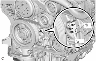
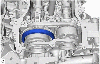
- Turn the crankshaft clockwise to align the timing mark (cutout) on the crankshaft pulley with the "0" timing mark on the timing chain cover assembly.
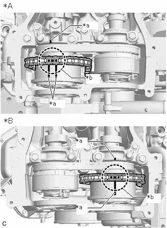
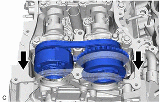
*a Timing Mark (Cutout) *b "0" Timing Mark - Check that the timing marks of the camshaft timing gear assemblies are aligned with the timing marks of the camshaft bearing caps as shown in the illustration.
HINT:
If the marks are not aligned, turn the crankshaft again to align the marks.
*A for Bank 2 *B for Bank 1 *a Timing Mark *b Paint Mark - Place paint marks on the timing marks and sprockets of each camshaft timing gear assembly and on the links of the chain sub-assembly.
HINT:
Be sure to place the paint marks on 2 links of the chain sub-assembly and on the sprockets of the camshaft timing gear assemblies at the locations of the timing marks of the camshaft timing gear assemblies.
- Turn the crankshaft clockwise to align the timing mark (cutout) on the crankshaft pulley with the "0" timing mark on the timing chain cover assembly.
- REMOVE NO. 1 CHAIN TENSIONER ASSEMBLY
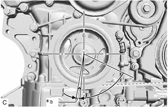
- Turn the crankshaft approximately 30° counterclockwise so that there is some slack in the chain sub-assembly.
HINT:
This prevents the valves and pistons from interfering with each other.
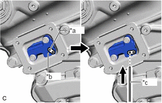
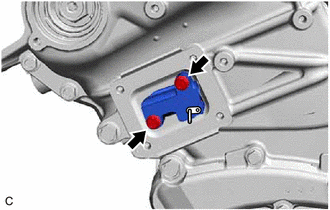
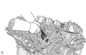
- Align the hole in the lever of the No. 1 chain tensioner assembly with the hole in the tensioner body as shown in the illustration, and then insert a pin with a diameter of 1.0 mm (0.0394 in.) into the hole.
*a Lever Hole *b Tensioner Body *c Pin NOTE:Check that the pin is locked.
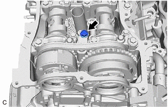
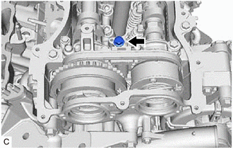
- Turn the crankshaft clockwise to align the timing mark (cutout) on the crankshaft pulley with the "0" timing mark on the timing chain cover assembly.
*a Timing Mark (Cutout) *b "0" Timing Mark - Remove the 2 bolts and No. 1 chain tensioner assembly from the cylinder head sub-assembly.NOTE:
Do not drop the No. 1 chain tensioner assembly or bolts into the timing chain cover assembly.
- Turn the crankshaft approximately 30° counterclockwise so that there is some slack in the chain sub-assembly.
- DISCONNECT CHAIN SUB-ASSEMBLY (for Bank 1)
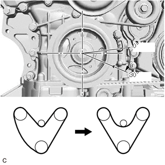
- Turn the crankshaft clockwise until it is in the position shown in the illustration so that there is some slack in the chain sub-assembly between the banks.WARNING:
As the camshafts may turn suddenly, do not touch the camshafts or camshaft timing gears.
HINT:
When turning the crankshaft, engine oil may spray out of the oil holes.
- Turn the crankshaft clockwise until it is in the position shown in the illustration so that the chain sub-assembly can be removed easily.
HINT:
When turning the crankshaft, engine oil may spray out of the oil holes.
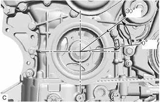
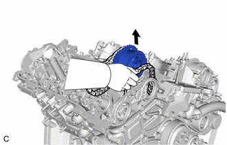
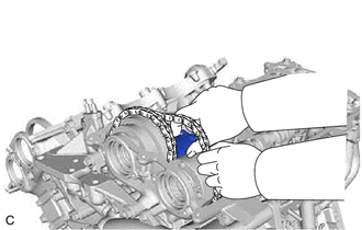
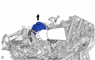
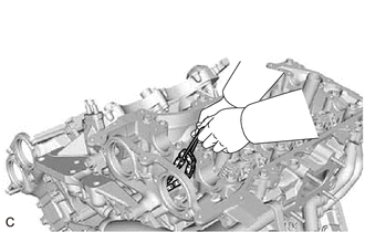
*a 5 to 10° - Remove the chain sub-assembly from the sprocket of the camshaft timing gear assembly and set it on the camshaft timing gear assembly.WARNING:
As the camshaft may turn suddenly and pinch your fingers when the chain sub-assembly is removed, pinch the chain sub-assembly and lift it upward to remove it from the sprocket.
- Turn the crankshaft clockwise until it is in the position shown in the illustration so that there is some slack in the chain sub-assembly between the banks.
- SEPARATE NO. 2 CHAIN TENSIONER ASSEMBLY
- REMOVE CAMSHAFT TIMING GEAR BOLT (for Intake Side of Bank 1)
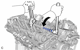
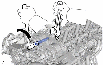
- Use a wrench to hold the hexagonal portion of the camshaft and remove the camshaft timing gear bolt from the camshaft timing gear assembly.
*a Hold 
Turn NOTE:- Be careful not to damage the camshaft, camshaft housing sub-assembly or spark plug tube with the wrench.
- If the camshaft timing gear bolt has been struck or dropped, replace it.
- Use a wrench to hold the hexagonal portion of the camshaft and remove the camshaft timing gear bolt from the camshaft timing gear assembly.
- REMOVE CAMSHAFT TIMING GEAR BOLT (for Exhaust Side of Bank 1)
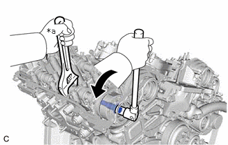
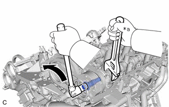
- Use a wrench to hold the hexagonal portion of the No. 2 camshaft and remove the camshaft timing gear bolt from the camshaft timing exhaust gear assembly.NOTE:
- Be careful not to damage the No. 2 camshaft, camshaft housing sub-assembly or spark plug tube with the wrench.
- If the camshaft timing gear bolt has been struck or dropped, replace it.
*a Hold Turn
- Use a wrench to hold the hexagonal portion of the No. 2 camshaft and remove the camshaft timing gear bolt from the camshaft timing exhaust gear assembly.
- REMOVE CAMSHAFT BEARING CAP (for Bank 1)
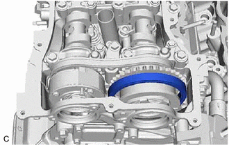
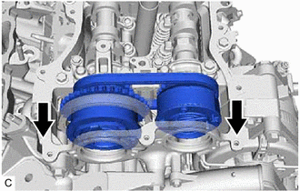
- Slide the camshaft timing gear assembly and camshaft timing exhaust gear assembly as shown in the illustration.
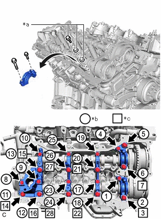
- Remove the bolts and camshaft bearing caps in the order shown in the illustration. Immediately after removing a camshaft bearing cap, install replacement bolts and washers in the order shown in the illustration.
Torque: 10 N.m (102 kgf/cm, 7 ft.lbf)
NOTE:- Do not install the camshaft bearing caps when installing replacement bolts and washers.
- Be sure to follow the numerical order when performing this procedure.
- Do not allow replacement bolts or washers to contact the camshaft.
- Do not drop replacement bolts or washers into the cylinder head sub-assembly.
HINT:
- Arrange the removed parts so that they can be reinstalled in their original locations.
- Part number for replacement bolts: 91551-F0850 (9 bolts)
- Part number for replacement washers: 90201-12028 (18 washers)
 Courtesy of © TOYOTA, LICENSE AGREEMENT TMS1002
*a Replacement Bolt and Washer *b Part Removal *c Replacement Bolt and Washer Installation
- Slide the camshaft timing gear assembly and camshaft timing exhaust gear assembly as shown in the illustration.
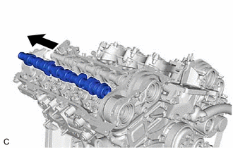
- REMOVE NO. 2 CAMSHAFT
- REMOVE CAMSHAFT
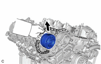
- REMOVE CAMSHAFT TIMING EXHAUST GEAR ASSEMBLY (for Bank 1)
- REMOVE CAMSHAFT TIMING GEAR ASSEMBLY (for Bank 1)
- DISCONNECT CHAIN SUB-ASSEMBLY (for Bank 2)
- Turn the crankshaft counterclockwise to align the timing mark (cutout) on the crankshaft pulley with the "0" timing mark on the timing chain cover assembly.
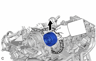
*a Timing Mark (Cutout) *b "0" Timing Mark - Remove the chain sub-assembly from the sprocket of the camshaft timing gear assembly and set it on the camshaft timing gear assembly.WARNING:
As the camshaft may turn suddenly and pinch your fingers when the chain sub-assembly is removed, pinch the chain sub-assembly and lift it upward to remove it from the sprocket.
- Turn the crankshaft counterclockwise to align the timing mark (cutout) on the crankshaft pulley with the "0" timing mark on the timing chain cover assembly.
- SEPARATE NO. 3 CHAIN TENSIONER ASSEMBLY
- REMOVE CAMSHAFT TIMING GEAR BOLT (for Intake Side of Bank 2)
- Use a wrench to hold the hexagonal portion of the No. 3 camshaft sub-assembly and remove the camshaft timing gear bolt from the camshaft timing gear assembly.
*a Hold Turn NOTE:- Be careful not to damage the No. 3 camshaft sub-assembly, camshaft housing sub-assembly LH or spark plug tube with the wrench.
- If the camshaft timing gear bolt has been struck or dropped, replace it.
- Use a wrench to hold the hexagonal portion of the No. 3 camshaft sub-assembly and remove the camshaft timing gear bolt from the camshaft timing gear assembly.
- REMOVE CAMSHAFT TIMING GEAR BOLT (for Exhaust Side of Bank 2)
- Use a wrench to hold the hexagonal portion of the No. 4 camshaft sub-assembly and remove the camshaft timing gear bolt from the camshaft timing exhaust gear assembly.
*a Hold Turn NOTE:- Be careful not to damage the No. 4 camshaft sub-assembly, camshaft housing sub-assembly LH or spark plug tube with the wrench.
- If the camshaft timing gear bolt has been struck or dropped, replace it.
- Use a wrench to hold the hexagonal portion of the No. 4 camshaft sub-assembly and remove the camshaft timing gear bolt from the camshaft timing exhaust gear assembly.
- REMOVE CAMSHAFT BEARING CAP (for Bank 2)
- Slide the camshaft timing gear assembly and camshaft timing exhaust gear assembly as shown in the illustration.
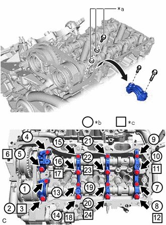
- Remove the bolts and camshaft bearing caps in the order shown in the illustration. Immediately after removing a camshaft bearing cap, install replacement bolts and washers in the order shown in the illustration.
Torque: 10 N.m (102 kgf/cm, 7 ft.lbf)
NOTE:- Do not install the camshaft bearing caps when installing replacement bolts and washers.
- Be sure to follow the numerical order when performing this procedure.
- Do not allow replacement bolts or washers to contact the camshaft.
- Do not drop replacement bolts or washers into the cylinder head LH.
HINT:
- Arrange the removed parts so that they can be reinstalled in their original locations.
- Part number for replacement bolts: 91551-F0850 (8 bolts)
- Part number for replacement washers: 90201-12028 (16 washers)
 Courtesy of © TOYOTA, LICENSE AGREEMENT TMS1002
*a Replacement Bolt and Washer *b Part Removal *c Replacement Bolt and Washer Installation
- Slide the camshaft timing gear assembly and camshaft timing exhaust gear assembly as shown in the illustration.
- REMOVE NO. 4 CAMSHAFT SUB-ASSEMBLY
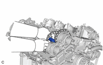
- While lifting up the camshaft timing exhaust gear assembly, remove the No. 3 chain tensioner assembly.
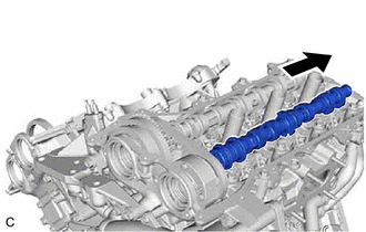
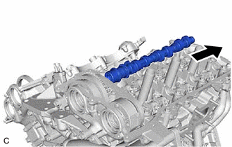
- Lift up the rear of the No. 4 camshaft sub-assembly so that it is at an angle.
- Pull the No. 4 camshaft sub-assembly as shown in the illustration to remove it from the camshaft timing exhaust gear assembly.
- While lifting up the camshaft timing exhaust gear assembly, remove the No. 3 chain tensioner assembly.
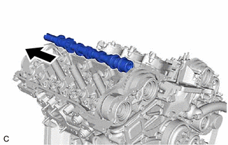
- REMOVE NO. 3 CAMSHAFT SUB-ASSEMBLY
- REMOVE CAMSHAFT TIMING EXHAUST GEAR ASSEMBLY (for Bank 2)
- REMOVE CAMSHAFT TIMING GEAR ASSEMBLY (for Bank 2)