Installation [10/2022 - ]: Procedure
- INSTALL REAR DRIVE SHAFT SNAP RING
- Install a new rear drive shaft snap ring.NOTE:
Face the end gap of the rear drive shaft snap ring downward.
- Install a new rear drive shaft snap ring.
- INSTALL REAR DRIVE SHAFT ASSEMBLY
- Coat the rear drive shaft snap ring of the rear drive shaft inboard joint assembly with MP grease.
- Coat the splines of the rear drive shaft inboard joint assembly with Toyota genuine differential gear oil LX.
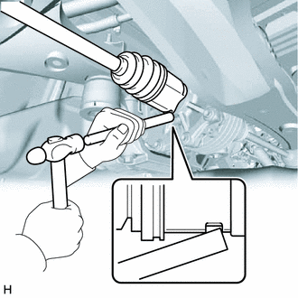
- Align the inboard joint splines, and using a brass bar and a hammer, install the rear drive shaft assembly.NOTE:
- Face the end gap of the rear drive shaft snap ring downward.
- Do not damage the rear drive shaft oil seal or transmission coupling dust seal.
- Do not damage the rear drive shaft inboard joint boot.
- Make sure to center the rear drive shaft assembly during installation to prevent damage to the rear drive shaft snap ring.
HINT:
Confirm whether the drive shaft is securely driven in by checking the reaction force and sound.
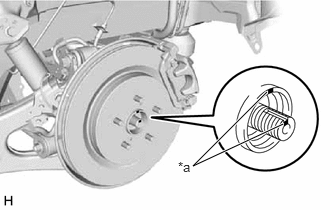
- Align the matchmarks and install the rear drive shaft assembly to the rear axle hub and bearing assembly.NOTE:
- Do not damage the rear disc brake dust cover sub-assembly.
- Do not damage the rear drive shaft outboard joint boot.
- Check that there is no foreign matter on the contact surfaces.
- Do not push the rear axle carrier sub-assembly towards the outside of the vehicle any further than necessary.
*a Matchmark
- TEMPORARILY INSTALL REAR UPPER CONTROL ARM ASSEMBLY
Refer to PROCEDURE - Step 19
- TEMPORARILY INSTALL REAR NO. 1 SUSPENSION ARM ASSEMBLY
Refer to PROCEDURE - Step 7
- TEMPORARILY INSTALL REAR NO. 2 SUSPENSION ARM ASSEMBLY
Refer to PROCEDURE - Step 2
- INSTALL REAR LOWER COIL SPRING INSULATOR
Refer to PROCEDURE - Step 3
- INSTALL REAR COIL SPRING
Refer to PROCEDURE - Step 4
- CONNECT REAR STABILIZER LINK ASSEMBLY
Refer to PROCEDURE - Step 7
- INSTALL REAR SKID CONTROL SENSOR
Refer to PROCEDURE - Step 14
- CONNECT NO. 2 PARKING BRAKE WIRE ASSEMBLY
Refer to PROCEDURE - Step 35
- INSTALL REAR AXLE SHAFT NUT
Refer to PROCEDURE - Step 11
- CONNECT REAR FLEXIBLE HOSE
Refer to PROCEDURE - Step 10
- STABILIZE SUSPENSION
Refer to PROCEDURE - Step 3
- INSTALL REAR NO. 1 SUSPENSION ARM ASSEMBLY
Refer to PROCEDURE - Step 7
- INSTALL REAR NO. 2 SUSPENSION ARM ASSEMBLY
Refer to PROCEDURE - Step 8
- INSTALL REAR UPPER CONTROL ARM ASSEMBLY
Refer to PROCEDURE - Step 6
- INSTALL REAR SUSPENSION ARM COVER
Refer to PROCEDURE - Step 9
- INSTALL TAIL EXHAUST PIPE ASSEMBLY (for RH Side)
Refer to PROCEDURE - Step 2
- INSTALL REAR WHEEL
Refer to INSTALLATION [10/2022 - ]
- INSTALL REAR NO. 2 SUSPENSION ARM ASSEMBLY
Refer to PROCEDURE - Step 8
- ADD DIFFERENTIAL OIL
for Dynamic Torque Control AWD: Refer to PROCEDURE - Step 3
for Dynamic Torque Vectoring AWD: Refer to PROCEDURE - Step 4
- INSPECT FOR DIFFERENTIAL OIL LEAK
- INSPECT FOR EXHAUST GAS LEAK (for RH Side)
Refer to PROCEDURE - Step 3
- INSPECT AND ADJUST REAR WHEEL ALIGNMENT
Refer to ADJUSTMENT [10/2022 - 11/2023] , or refer to ADJUSTMENT [11/2023 - 11/2024] , or refer to ADJUSTMENT [11/2024 - ]
- CHECK FOR SPEED SENSOR SIGNAL
Refer to TEST MODE PROCEDURE [12/2019 - 11/2023] , or refer to TEST MODE PROCEDURE [11/2023 - ]
- PERFORM INITIALIZATION
- Parking assist monitor system calibration:
Refer to CALIBRATION [10/2022 - ]
- Panoramic view monitor system calibration:
Refer to CALIBRATION [10/2022 - 11/2023] , or refer to CALIBRATION [11/2023 - ]
- Lighting system initialization (w/ AFS):
Refer to INITIALIZATION [12/2019 - 11/2023] , or refer to INITIALIZATION [11/2023 - ]
- SFI system initialization:
Refer to INITIALIZATION [10/2022 - ]
- Parking assist monitor system calibration: