Installation [12/2019 - 10/2022]: Procedure
- INSTALL NO. 2 CYLINDER HEAD GASKET
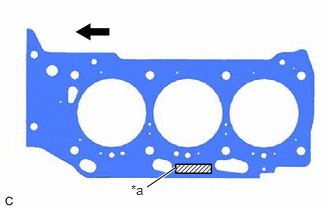
- Place a new No. 2 cylinder head gasket on the cylinder block sub-assembly as shown in the illustration.
*a Lot No. 
Front of Engine NOTE:- Remove any oil from the contact surfaces.
- Make sure to install the No. 2 cylinder head gasket in the correct direction.
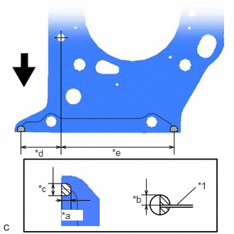
- Apply seal packing to the No. 2 cylinder head gasket as shown in the illustration.
Seal Packing
Toyota Genuine Seal Packing Black, Three Bond 1207B or equivalent
NOTE:- Remove any oil from the contact surfaces.
- Install the No. 2 cylinder head gasket within 3 minutes and tighten the cylinder head set bolts within 15 minutes of applying seal packing.
*1 No. 2 Cylinder Head Gasket *a 5.0 to 7.0 mm (0.197 to 0.276 in.) *b 3.0 to 5.0 mm (0.118 to 0.197 in.) *c 7.0 to 9.0 mm (0.276 to 0.354 in.) *d 38.2 mm (1.50 in.) *e 110.0 mm (4.33 in.) Front of Engine 
Seal Packing
- Place a new No. 2 cylinder head gasket on the cylinder block sub-assembly as shown in the illustration.
- INSTALL CYLINDER HEAD LH
Refer to PROCEDURE - Step 4
- INSTALL CYLINDER HEAD GASKET
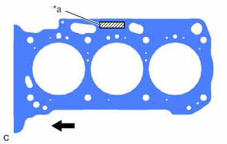
- Place a new cylinder head gasket on the cylinder block sub-assembly as shown in the illustration.
*a Lot No. Front of Engine NOTE:- Remove any oil from the contact surfaces.
- Make sure to install the cylinder head gasket in the correct direction.
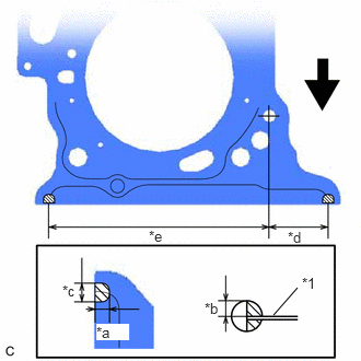
- Apply seal packing to the cylinder head gasket as shown in the illustration.
Seal Packing
Toyota Genuine Seal Packing Black, Three Bond 1207B or equivalent
NOTE:- Remove any oil from the contact surfaces.
- Install the cylinder head gasket within 3 minutes and tighten the cylinder head set bolts within 15 minutes of applying seal packing.
*1 Cylinder Head Gasket *a 5.0 to 7.0 mm (0.197 to 0.276 in.) *b 3.0 to 5.0 mm (0.118 to 0.197 in.) *c 7.0 to 9.0 mm (0.276 to 0.354 in.) *d 38.5 mm (1.52 in.) *e 144.0 mm (5.67 in.) Front of Engine Seal Packing
- Place a new cylinder head gasket on the cylinder block sub-assembly as shown in the illustration.
- INSTALL CYLINDER HEAD SUB-ASSEMBLY
Refer to PROCEDURE - Step 6
- INSTALL WATER OUTLET
Refer to PROCEDURE - Step 62
- INSTALL VALVE STEM CAP
Refer to PROCEDURE - Step 10
- INSTALL VALVE LASH ADJUSTER ASSEMBLY
Refer to PROCEDURE - Step 11
- INSTALL NO. 1 VALVE ROCKER ARM SUB-ASSEMBLY
Refer to PROCEDURE - Step 12
- INSTALL NO. 1 CHAIN VIBRATION DAMPER
Refer to PROCEDURE - Step 40
- INSTALL NO. 2 CHAIN VIBRATION DAMPER
Refer to PROCEDURE - Step 39
- INSTALL SENSOR WIRE
Refer to PROCEDURE - Step 20
- INSTALL NO. 3 CAMSHAFT SUB-ASSEMBLY
Refer to PROCEDURE - Step 15
- INSTALL NO. 4 CAMSHAFT SUB-ASSEMBLY
Refer to PROCEDURE - Step 16
- INSTALL CAMSHAFT BEARING CAP (for Bank 2)
Refer to PROCEDURE - Step 17
- SET CAMSHAFT TIMING GEAR ASSEMBLY, CAMSHAFT TIMING EXHAUST GEAR ASSEMBLY AND NO. 2 CHAIN SUB-ASSEMBLY (for Bank 2)
Refer to PROCEDURE - Step 19
- TEMPORARILY INSTALL CAMSHAFT TIMING GEAR BOLT (for Intake Side of Bank 2)
See step 8
- TEMPORARILY INSTALL CAMSHAFT TIMING GEAR BOLT (for Exhaust Side of Bank 2)
See step 9
- INSTALL CAMSHAFT HOUSING SUB-ASSEMBLY LH
Refer to PROCEDURE - Step 22
- TIGHTEN CAMSHAFT TIMING GEAR BOLT (for Intake Side of Bank 2)
Refer to PROCEDURE - Step 23
- TIGHTEN CAMSHAFT TIMING GEAR BOLT (for Exhaust Side of Bank 2)
Refer to PROCEDURE - Step 24
- INSTALL CAMSHAFT
Refer to PROCEDURE - Step 27
- INSTALL NO. 2 CAMSHAFT
Refer to PROCEDURE - Step 28
- INSTALL CAMSHAFT BEARING CAP (for Bank 1)
Refer to PROCEDURE - Step 29
- SET CAMSHAFT TIMING GEAR ASSEMBLY, CAMSHAFT TIMING EXHAUST GEAR ASSEMBLY AND NO. 2 CHAIN SUB-ASSEMBLY (for Bank 1)
Refer to PROCEDURE - Step 31
- TEMPORARILY INSTALL CAMSHAFT TIMING GEAR BOLT (for Intake Side of Bank 1)
See step 21
- TEMPORARILY INSTALL CAMSHAFT TIMING GEAR BOLT (for Exhaust Side of Bank 1)
See step 22
- INSTALL CAMSHAFT HOUSING SUB-ASSEMBLY
Refer to PROCEDURE - Step 34
- TIGHTEN CAMSHAFT TIMING GEAR BOLT (for Intake Side of Bank 1)
Refer to PROCEDURE - Step 35
- TIGHTEN CAMSHAFT TIMING GEAR BOLT (for Exhaust Side of Bank 1)
Refer to PROCEDURE - Step 36
- INSTALL NO. 3 CHAIN TENSIONER ASSEMBLY
Refer to PROCEDURE - Step 18
- INSTALL NO. 2 CHAIN TENSIONER ASSEMBLY
Refer to PROCEDURE - Step 30
- INSTALL CHAIN SUB-ASSEMBLY
Refer to PROCEDURE - Step 42
- INSTALL CHAIN TENSIONER SLIPPER
Refer to PROCEDURE - Step 43
- INSTALL NO. 1 CHAIN TENSIONER ASSEMBLY
Refer to PROCEDURE - Step 44
- INSPECT VALVE TIMING
Refer to PROCEDURE - Step 45
- INSTALL TIMING CHAIN COVER ASSEMBLY
Refer to PROCEDURE - Step 1
- INSTALL TIMING CHAIN CASE OIL SEAL
See step 1
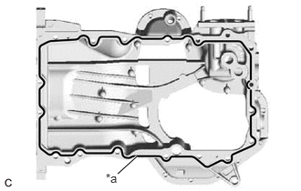
- INSTALL OIL PAN SUB-ASSEMBLY
- Install 2 new oil pan gaskets to the timing chain cover assembly.
- Apply seal packing in a continuous line as shown in the illustration.
*a Seal Packing Seal Packing
Toyota Genuine Seal Packing Black, Three Bond 1207B or equivalent
Seal Packing Diameter
3.0 to 4.0 mm (0.118 to 0.157 in.)
NOTE:- Remove any oil from the contact surfaces.
- Install the oil pan sub-assembly within 3 minutes of applying seal packing.
- Do not start the engine for at least 2 hours after installation.
- Install the oil pan sub-assembly with the 16 bolts and 2 nuts in the order shown in the illustration.
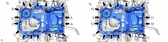
 Courtesy of © TOYOTA, LICENSE AGREEMENT TMS1002
*a Torque *b Bolt and Nut Tightening Order Bolt Nut Bolt (A)
Torque: 10 N.m (102 kgf/cm, 7 ft.lbf)
Bolt (B), (C), (D)
Torque: 21 N.m (214 kgf/cm, 15 ft.lbf)
Nut
Torque: 21 N.m (214 kgf/cm, 15 ft.lbf)
Bolt Length
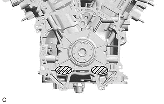
Item Length Bolt (A) 16 mm (0.630 in.) Bolt (B) 45 mm (1.77 in.) Bolt (C) 25 mm (0.984 in.) Bolt (D) 70 mm (2.76 in.) - Wipe off any excess seal packing with a clean piece of cloth.NOTE:
Do not allow seal packing to contact the No. 1 crankshaft position sensor plate.
Wipe off the Seal Packing
- INSTALL OIL STRAINER SUB-ASSEMBLY
Refer to PROCEDURE - Step 54
- INSTALL NO. 2 OIL PAN SUB-ASSEMBLY
Refer to PROCEDURE - Step 55
- INSTALL OIL COOLER PIPE
Refer to PROCEDURE - Step 64
- INSTALL OIL COOLER ASSEMBLY
Refer to PROCEDURE - Step 1
- INSTALL SPARK PLUG TUBE GASKET
Refer to PROCEDURE - Step 59
- INSTALL CYLINDER HEAD COVER SUB-ASSEMBLY LH
Refer to PROCEDURE - Step 60
- INSTALL CYLINDER HEAD COVER SUB-ASSEMBLY
Refer to PROCEDURE - Step 61
- INSTALL SENSOR WIRE
Refer to PROCEDURE - Step 9
- INSTALL CRANKSHAFT POSITION SENSOR PROTECTOR
Refer to PROCEDURE - Step 2
- INSTALL CAMSHAFT TIMING OIL CONTROL SOLENOID ASSEMBLY (for Intake Side of Bank 2)
Refer to PROCEDURE - Step 1
- INSTALL CAMSHAFT TIMING OIL CONTROL SOLENOID ASSEMBLY (for Exhaust Side of Bank 2)
Refer to PROCEDURE - Step 6
- INSTALL CAMSHAFT TIMING OIL CONTROL SOLENOID ASSEMBLY (for Exhaust Side of Bank 1)
Refer to PROCEDURE - Step 3
- INSTALL CAMSHAFT TIMING OIL CONTROL SOLENOID ASSEMBLY (for Intake Side of Bank 1)
Refer to PROCEDURE - Step 5
- INSTALL WATER INLET WITH THERMOSTAT SUB-ASSEMBLY
Refer to PROCEDURE - Step 1
- CONNECT WATER BY-PASS HOSE
Refer to PROCEDURE - Step 2
- INSTALL FRONT NO. 1 ENGINE MOUNTING BRACKET LH
Refer to PROCEDURE - Step 76
- INSTALL CRANKSHAFT PULLEY
See step 2
- INSTALL WATER FILLER BRACKET
Refer to PROCEDURE - Step 1
- INSTALL WIRE HARNESS CLAMP BRACKET
Refer to PROCEDURE - Step 2
- INSTALL NO. 5 CYLINDER BLOCK INSULATOR
Refer to PROCEDURE - Step 4
- INSTALL ENGINE OIL LEVEL DIPSTICK GUIDE
Refer to PROCEDURE - Step 5
- INSTALL WATER PUMP PULLEY
Refer to PROCEDURE - Step 2
- INSTALL V-RIBBED BELT TENSIONER ASSEMBLY
Refer to PROCEDURE - Step 7
- INSTALL NO. 2 IDLER PULLEY SUB-ASSEMBLY
Refer to PROCEDURE - Step 3
- INSTALL COMPRESSOR AND MAGNETIC CLUTCH
Refer to PROCEDURE - Step 2
- INSTALL GENERATOR ASSEMBLY
Refer to PROCEDURE - Step 1
- INSTALL V-RIBBED BELT
Refer to PROCEDURE - Step 1
- INSTALL VACUUM PUMP ASSEMBLY
Refer to PROCEDURE - Step 1
- INSTALL IGNITION COIL ASSEMBLY
Refer to PROCEDURE - Step 2
- INSTALL KNOCK CONTROL SENSOR
Refer to INSTALLATION [12/2019 - 10/2022]
- INSTALL ENGINE HANGERS
See step 61 [12/2019 - 09/2020], or see step 61 [09/2020 - 10/2022]
- REMOVE ENGINE ASSEMBLY FROM ENGINE STAND
Refer to INSTALLATION [12/2019 - 09/2020] , or refer to INSTALLATION [09/2020 - 10/2022]